
Wireless device
The wireless device contains both the radio and networking electronics. Implemented in a robust all-weather metal enclosure, this equipment can be used to create point-to-point and point-to-multipoint wireless links at long distances. The wireless device is supplied in the
- with integrated antenna 16 dBi (E5-BSI, E6-BSI);
- with integrated antenna 21 dBi (E5-BSQ);
- with two N-type ports for an external antenna (E5-BSE, E6-BSE).
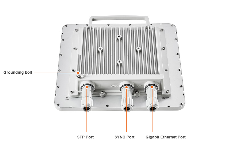
Base Station Sectors Interfaces
Base station sectors have ports:
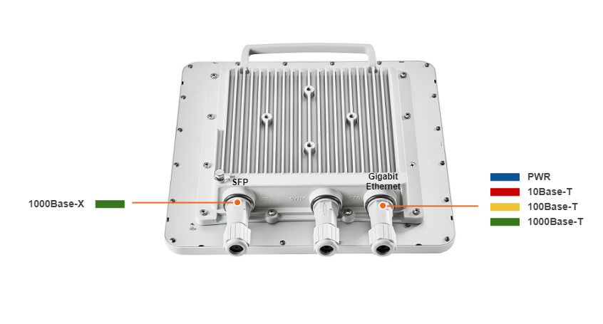
- 1x Gigabit Ethernet port (10/100/1000 Base‑T), RJ‑45 connector: Data + Power.
- 1x SFP port: Data.
- 1x SYNC port for AUX‑ODU‑SYNC connection.
| Interface | Description |
|---|
| Gigabit Ethernet | RJ-45 socket for connecting to power supply and data transmission. The network connection to the wireless device is made via a 1000Base-T (Gigabit) Ethernet connection. Power is provided to the device over the 1000Base-T Ethernet connection using a standard IEEE 802.3at passive PoE power supply. |
|---|
| SFP | External optical Gigabit port for plugging of the optical SFP transceiver module. |
|---|
| SYNC | RJ-45 socket for connecting to synchronization unit AUX‑ODU‑SYNC. |
|---|
|
LEDs
Power and wired statuses indication is performed via glassy plug of the cable gland. |
| LED | State | Status | Description |
|---|
Gigabit Ethernet SFP | Flash | Initialization | The LEDs on both ports light up with white on second. Then LEDs check is performed: red, blue, green are lightened up sequentially. |
|---|
| Flash | Loading | Only for Gigabit Ethernet port: at the beginning green is lightened a few seconds, on the second loading stage switches to blue. | | ON/Blue | Power | Only for Gigabit Ethernet port. | | ON/Red | Speed 10 Mbps | Only for Gigabit Ethernet port. | | ON/Yellow | Speed 100 Mbps | Only for Gigabit Ethernet port. | | ON/Green | Speed 1000 Mbps |
| | ON/Green | ERConsole stage | Port with the established link lights up with green, the second port remains blue. |
|
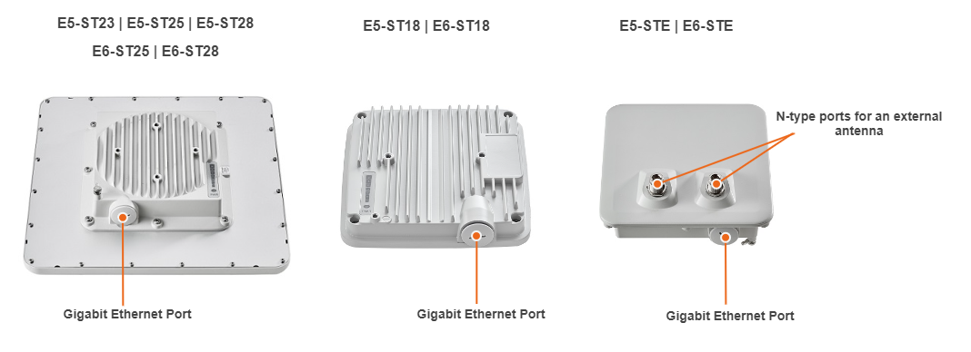
Subscriber Terminals and point-to-point devices
- with integrated antenna 18 dBi;
- with integrated antenna 23 dBi;
- with integrated antenna 25 dBi;
- with integrated antenna 28 dBi;
- with two N-type ports for an external antenna.
Subscriber Terminals and PTP devices Interfaces
RJ-45 socket for connecting to power supply and network via the PoE power supply. The network connection to the ODU is made via a 1000Base-T (Gigabit) Ethernet connection. Power is provided to the ODU over the 1000Base-T Ethernet connection using a standard IEEE 802.3at passive PoE power supply.
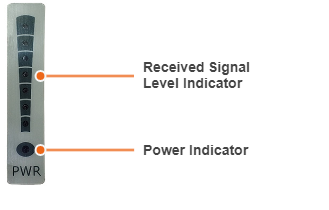
LED Panel
PWR - power indicators will light red when the device is connected to a power source, yellow when 10/100 Mbps wired connection appears and green when 1000 Mbps wired connection appears. Other indicators are used to perform coarse antenna alignment. The more indicators are on, the better wireless connection is established. The blinking indicator means an intermediate state. The more often the indicator blinks the higher level connection is established.
Part number description