
In the "Link Settings" section you can configure the parameters for the Radio interface, for the Pseudo Radio interface and for the Join function:
The "Link Setting" section is consist from the following subsections:
"rf6.0" subsection 
This subsection is used for:
Radio link settings 
"rf6.0" subsection is divided in two zones:
- The panel that describes global link settings, in the left side of the page
- The panel that describes the radio channel settings which are currently in use, in the right side of the page.
In a point-to-multipoint topology, several profiles can be configured on the Slave device (with parameters for connecting to each base station sector). A subscriber terminal can connect to more than one base station, both in nomadic or mobile mode and in a fixed mode for redundancy purposes (a separate profile for each base station). When trying to establish a wireless connection, the subscriber terminal selects a base station with parameters that provide the best connection quality (RSSI, signal-to-noise ratio, bitrate, errors number, retries, etc.) If connection with the base station is lost, the subscriber terminal will not try to reconnect to it, but will evaluate the signal parameters of all available base stations sectors.
The "Frequency roaming" function is enabled by default (the "auto" option of the Frequency parameter), and allows the subscriber terminal with automatic frequency selection (if it has appropriate radio profiles):
- Automatically switch from the main base station (roamingleader) to the backup.
- Automatically switch between different base stations while moving.
- Automatically switch to a new base station frequency if the current base station frequency has changed.
During frequency roaming process the traffic transmission does not stop.The radio link parameters are described in the table:
| Parameter | Description |
|---|
| General Settings |
|---|
| Enable link | - Enable/disable wireless link (enabled by default)
| | Type | - Set the node type to Master or Slave
- Master: can establish connections with all other types of nodes. It is able to form a network of any topology with other master nodes. A master node is usually used in the configuration of the both sides of the PtP links and in the configuration of the BS for the PtMP links
- Slave: can only connect to master type nodes (the connection cannot be established between two slave nodes). A slave node is usually used in the configuration of the CPE.
| MultiBS (Slave) | - Enabled: when the link parameters deteriorate, the CPE will disconnect from the current base station and try to find the sector with the best parameters values
- Disabled: the CPE will keep the connection with a current base station until the signal is completely lost
- It is available for Slave node only
| | Mode | This setting determines the operating mode of the device. The operating mode is determined by the application of this node in the network. - Fixed - the node has a fixed position in the network, it is constantly on. It is a core node of the network. Recalculation of the MINT connections cost in this mode will occur every 3 seconds.
- Nomadic - the node can change its geographic location, but data exchange within the network, as a rule, occurs when the node does not move. The cost of MINT connections will be recalculated every 1.5 seconds.
- Mobile - the node often moves. Data exchange take place during the movement. Recalculation of the cost of MINT connections will occur every second.
| | R5000 Compatibility mode | Enable/disable compatibility with InfiLINK 2x2 / InfiMAN 2x2 family device Recommendations how to upgrade the wireless network from the R5000 series to Evolution and limitations that must be taken into account when R5000 and Evolution devices operate together in one network are described at "Upgrade from R5000 to Evolution". |
| VBR (Slave) | - The mode at which the service information is carried out at above a minimum bitrate (if possible)
| Radar Detection (Slave) | - Enable/disable "Radar Detection" features (a special license with the country code is necessary)
- The DFS system performs radar detection and if a radar signal is detected, that frequency is marked as occupied and it can be used again only after a hold-down interval (the link is switched automatically to another frequency)
| Max Links (Master) | - Maximum allowed number of connected CPEs ( in the case of radio connection ) . When this value is reached, other attempts to connect to the base station will be rejected
| Use AUX-ODU-SYNC (Master) | - Enable/disable external synchronization unit, in seconds
| Sync Hold Time (Master) | - Standalone downtime in case of external synchronization unit disable. Value "0" (zero) disables this parameter control, command to work always is set
- In case of external synchronization unit disable, the devices can synchronously work for some time using own clock signal generator. However, eventually, because of generators frequencies mismatch, the time discrepancy can reach unacceptable values and devices will begin to interfere with each other. In this case, through fixed time the device will stop the transmitter and will stop operation of TDMA until synchronization unit enable
| Frame Size (Master) | - Set the time slot duration (in milliseconds)
- Consists of transfer time, reception time and guard intervals
- The range is from 2 to 10 ms in increments of 0.1 ms
- The recommended values for links PtP at the balanced channel depending on channel width: 2-2,5 ms for 40 and 80 MHz, 2-4 ms for 20 MHz, 3-5 ms for 10 MHz
- The recommended values for links PtMP depending on channel width: 5 ms for 20, 40 and 80MHz
| Auto (Master)
| - This option works only for links "PtP" and allows to reduce the window size and a delay at absence or a small amount of traffic. Automatically selects the frame size
| Turbo (Master) | - Increase the throughput in case of link degradation due to errors in the radio. The sliding window of the ARQ algorithm are extended from three to five frames, which increases its efficiency.
| DL/UL ratio (%) (Master) | - Set the DL percentage of the time slot
- The range is from 20 to 80% in increments of 1%
- The empty field enables the mode of flexible DL/UL ratio adjustment depending on traffic load
- Real accepted values depend on the used bandwidth, the frame size and the used modulations. To determine the established value acceptability it is necessary to control parameters (Tx Time Limit/Rx Time Limit) in radio interface statistics. Any of these parameters shall not be less than zero. In the PtMP system with a large number of clients, the ratio of real throughput in this or other way does not match the established DL/UL value. Uplink performance will always be less, because of big overheads of the uplink traffic servicing. In case of a large number of clients value more than 65% practically do not lead to throughput increase in Downlink. Rated speed in Uplink and Downlink (Rx Cap/Tx Cap) is reached only in case of sector full and balanced load by all clients
| Max Distance (Km) (Master) | - Set the maximum operational distance (in kilometers)
- Has an impact on guard intervals duration
- The range is from 1 to 100 km in increments of 1 km
- It allows the system to calculate signal propagation time to the furthest subscriber and value of the guard interval between transmission and receiving phases. It is recommended to set 3-5 km more than really measured distance. In case of LOS condition violation or with a large number of reflections larger value as 10-20 km can be required
| STA RSSI (dBm) (Master) | - Set the target power of received radio signal from Slave node at the input of Master node
- The range is from -90 to -20 dBm in increments of 1
It allows to reduce the radiation influence from the subscriber units to the neighbor sector due to insufficient suppression of the antenna pattern back lobe To achieve maximum TDMA network performance it is important to obtain the highest possible signal level and modulation (bitrates), so transmitter power reducing is a necessary measure. If possible, it is better to try to reduce the impact of clients on neighbor sector (and vice versa), organizational measures (shielding, antennas diversity, etc.)
| | Regulatory Domain | - Allows to limit frequencies available for use on the device, in accordance with the requirements of local legislation
- In some regulatory domains DFS modes are restricted to use
- The list of available regulatory domains is determined by the license
| DFS (Master) | - Enable/disable DFS
- If “DFS only” is set, the DFS system monitors interferences but does not perform radar detection
- If "DFS with Radar Detection" is set, the DFS system monitors interferences and performs radar detection
- For the two radios base stations, the “Instant DFS” option is available (one of the two radios is used for DFS scanning, Radar detection and Spectrum analyzing)
Please note that, in some countries, switching “DFS off” and/or failing to detect public service radar signals are against the regulations and may result in legal action. |
| | Tx Power | - Set the output power of the radio interface
- Acts as a top limit for the output power control if the ATPC mechanism is turned on
- Two operating ranges of Tx power are available:
- “-10...10” (if chosen top limit is 10 dBm or less)
- “0...27” (if chosen top limit is from 10.5 dBm to 27 dBm)
- By default, it is turned on (it is strongly recommended to remains “on”)
- The offset parameter is used to adjust the thresholds
| | Node Name | - Set the name for this node in the network
- By default, it is the "Unknown" node
- This node name will appear on the neighbor lists
| | Scrambling | - Enable/disable the data scrambling to improve the connection stability (enabled by default)
| | Trap gateway | - Enable/disable gateway for SNMP-traps
| | Switch border | - Enable/disable the switch border mode. In this mode the unit operates as a "borderline" between the MINT domains, i.e. prevents the distribution of information about the switch groups and data transfer between these domains, while retaining all the capabilities of the MINT protocol (obtaining information about the whole MINT network, sending remote commands etc.)
| | Network Entry SNR (dB) | - "low" - this option sets the minimal signal level for the neighbor. Signal level is measured in dB above the noise threshold for the current bitrate. If the level gets lower than specified value the connection with a neighbor will be lost.
- "high" - this option sets the minimal SNR for a new neighbor. Signal level is measured in dB above the noise threshold for the current bitrate. If neighbor’s signal level is equal or higher than a specified value the node will consider this neighbor to be a candidate
| | Network Entry EVM (-dB) | - "high" - minimum EVM value required to establish a radio link between two devices. Value by defaut - 8.
- "low" - minimum EVM value at which the radio link between devices will not be broken. Value by default -0.
| | RX Attenuation | - The noise level measured by the radio module is calculated as the minimum received signal level (RSSI) in a certain period
- The "RX Attenuation" parameter allows manually raise noise threshold on several dB. In this case the radio module won't react to signals below the established threshold. In certain cases it gives the ability to be protected from the low signals interferences which disrupt the radio module as a result of capture effect. This effect is expressed in the fact that the radio module having captured the low signal from the foreign source, tries to strengthen it and to accept completely ignoring a strong signal from the client which has appeared later
- This parameter allows to protect the receiver from the powerful signal source overload
| Multicast Mode (Master) | - Traffic transmission mode:
- "Multicast" - conventional mode that uses modulation one step lower than the lowest modulation among the traffic receivers when transmitting the "multicast/broadcast" frames. In the case of "multicast" streams information from "IGMP Snooping" module is used to obtain a list of subscribers. Consequently, the list of all connected sector clients is used for the "broadcast" traffic.
- Transformation of "Multicast" to "Unicast". In case two or more clients are assigned to the same "multicast" stream a copy of source stream will be sent to each of them in the "Unicast" mode.
- "Unicast 2", "Unicast 3", "Unicast 4", "Unicast 5" - the number of subscribers limitation. Conventional "Multicast" mode will be used when the number is exceeded.
- "Unicast All" - transformation is always executed.
Transformation to "Unicast" requires memory data copying that increases CPU load. Besides, the use of "Unicast" streams increases the volume of transmitted traffic proportional to the number of subscribers and reduces the sector available throughput. "Unicast 3" mode is set by default. |
Transformation of "Multicast" to "Unicast" via CLI is described in the section "mint command". |
| | Authentication Mode | - Set the mode:
- "static" - the unit can establish connections only with units, which MAC-addresses are listed in the "Static Links" section
- public - the unit can establish connections with any other units which have the same security key and the corresponding wireless connection settings
- "remote" - centralized authentication mode with remote server (e.g. RADIUS or relay). In this mode any node can request the information from a remote authentication server (remote authentication server parameters are set using “AAA” command). This means that the node must have an access to this server (e.g. using IP)
| | ODR | Activate routing using the ODR protocol. The following modes are available: - "Disable" - routing using ODR is not performed.
- "Hub" - the device acts as a central node.
- "Spoke" - the device acts as a peripheral node.
The main advantage of ODR protocol is a network throughput efficient use. Part of the link throughput is usually used by the routing protocol to transmit service information, this part can be released by ODR using. The ODR protocol transmits the hosts IP prefixes using the MINT protocol at the data link layer. The ODR protocol can only be used in networks with star topology, where all nodes are connected to the central node only. An example of such a network is a point-to-multipoint topology, where each subscriber is connected only to a base station. | | OTA | Automatic updates in the MINT domain may be configured in the following modes: - “Disabled” - the device does not check if other devices in the MINT domain have a newer software versions.
- "Passive" - in case a newer software version is detected on one of the neighboring nodes, the device requests and updates the software. The device does not announce own software version.
- "Active" - the device announces its software version in the MINT domain, making it available to download by other nodes.
| | Log Level | | | Fixed Cost | - Allows to set fixed cost value to all routes passing through this interface
- The device will select the route with the lower cost, if any
| | Extra Cost | - Allows to add additional cost value to all routes passing through this interface
| | Join Cost | - Allows to add additional cost value to all routes passing through interfaces that are joined to this interface by the join option
| | MINT Failover | - Activate the failover function on this interface. For more information about this function proceed to the article "Link aggregation, balancing and redundancy"
- If the MAC address of a neighbor is specified, then the device will monitor the availability of this address. If the MAC field remains empty - the neighbor's address will be determined automatically
| | Current Settings |
|---|
| Channel Width | - Set the bandwidth of the radio interface in MHz
- It must be the same at both ends of the link
| | Frequency | - Set the radio interface frequency (in MHz)
- It must be the same at both ends of the link
- If it is set to “Auto”, the Slave node is scanning on all frequencies for the Master nodes
| | Frequency Range List | - Set the frequencies that are allowed to be chosen by the DFS mechanism (available only when the DFS system is enabled)
- It is available to support the legacy products
- Note that this option is different from the "Customer Frequency Grid" tool which allows narrowing down the frequency range available in the "Frequency" option from the Radio profile
| | Tx Bitrate | - Set the maximum operating bitrate of the radio interface
- Acts as a top limit for the bitrate if the Autobitrate mechanism is turned on
- By default, it is turned on (it is strongly recommended to remains “on”)
- Adjust the Autobitrate system thresholds when the remote SNR doesn’t have the normal level
| | Channel Type | | | Network SID | - Set the network system identifier (up to 8-digit HEX figure)
- It must be the same at both ends of the link
| | Node ID | - Set the device identification number
- The parameter is optional
- Node ID can be configured by the administrator for a better representation of a neighbors table (nodes within a wireless network)
| | Security Key | - Set the secret key word for encoding of the protocol messages
- It must be up to 64 characters long, without spaces
- It must be the same at both ends of the link
|
|
|
On each radio profile, the following options are available (for the Slave unit only):
- "Disable profile" check box disable a radio profile
- Add a new radio profile by clicking the «Add Profile» button
- Copy the radio profile values to a new radio profile by clicking the «Copy» button
- Remove the radio profile by clicking the «Remove» button.
Frequency limitation 
The licensed frequencies range per each bandwidth is displayed in the "rf6.0" subsection, in “Default Frequency Grid” fields. Changes to these default values can be performed in the “Customer Frequency Grid” fields; you can:
- Limit the licensed frequencies range per each bandwidth (see the screenshot below)
- Change the center frequency step (for example: 5920-6040/20 means that the step between the center frequencies from 5920 GHz and 6040 GHz is 20 MHz).
The changes performed in “Customer Frequency Grid” will be available in the “Frequency” drop down list from the radio profiles and in DFS page in “Frequency grid” field.
Setting channel type mode 
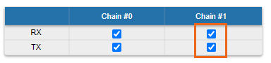
When Channel Type is set to “Single”, then Tx and/or Rx of Chain #1 (for horizontal polarization antenna) can be deactivated:
- "Chain #0" is connected to the port of the vertical polarized integrated antenna
Please note, the connectorized models have different the vertical and horizontal polarization correspondence to Chain #0 and Chain #1 channels. For E5-BSE, E6-BSE, E5-STE and E6-STE devices: - "Chain #0" is connected to the H-port on the enclosure
- "Chain #1" is connected to the V-port on the enclosure
|
If the "Single" mode is selected when, then "Chain #1" column can be disabled for transmission (TX) and / or reception (RX):
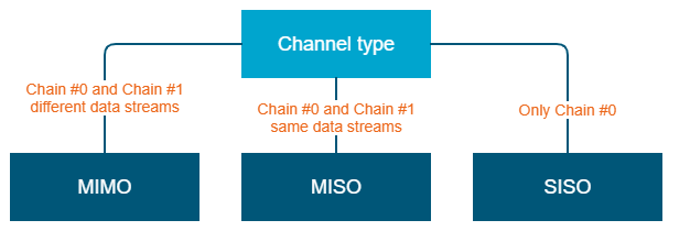
MIMO, MISO and SISO are defined from the perspective of the data sent by the local unit (not considering the number of physical antennas used for tx and rx like in the classical definition). Therefore, these represent local configuration options. For example, one stream of data can be sent by one chain (1 antenna) corresponding to SISO or the same stream can be sent by both chains (2 antennas) corresponding to MISO. |
Settings for "MIMO" mode
Different data streams are transmitted over "Chain #0" and "Chain #1". MIMO uses multiple antennas at both the transmitter and receiver side to improve communication performance and data is sent on both the horizontal and vertical polarizations (data is space-time coded - spatial multiplexing, to improve the reliability of data transmission):
| Channel Type | Dual |
|---|
| Radio Chain | #0 | #1 |
|---|
| Rx | | |
|---|
| Tx | | |
|---|
|
|
Settings for "MISO" mode
The same data streams are transmitted over "Chain #0" and "Chain #1", lowering the performance of the link, but enhancing the ability to transmit data in case of interference or obstacles in transmission path (a special mode of operation of MIMO devices used in NLOS conditions or in a noisy RF environment):
| Channel Type | Single |
|---|
| Radio Chain | #0 | #1 |
|---|
| Rx | | |
|---|
| Tx | | |
|---|
|
|
Settings for "SISO" mode
The data streams are transmitted over Chain #0 only, lowering the performance of the link, but increasing the link distance (transmitter operates with one antenna as does the receiver; there is no diversity and no additional processing for recomposing the Rx signal):
| Channel Type | Single |
|---|
| Radio Chain | #0 | #1 |
|---|
| Rx | | |
|---|
| Tx | | |
|---|
|
|
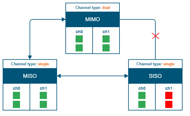
The picture below summarizes the link establishment between two units that are configured in different operational modes. As it can be noticed, only the combination MIMO – SISO is not functi
"prf" subsection
In the "prf" subsection, you can configure the pseudo-RF link as a MINT network node. The "prf" subsection is available for configurations only after at least one pseudo-RF interface has been created in "Network Settings" section. Pseudo-RF virtual interface is used to provide MINT-over-Ethernet. Every BS or CPE supports PRF interfaces. All parameters available in "prf" subsection are explained in "rf6.0" subsection above:
"Join" subsection
In the "Join" subsection, you can link two or more radio/pseudo-RF interfaces of one unit into one MINT domain. Each of these interfaces may act as an independent MINT network node. The "Join" subsection is available for configurations only after at least one pseudo-RF interface has been created in "Network Settings" section.
In order to join the interfaces, simply enable the check boxes of the corresponding interfaces, as shown in the screenshot below: