Successfully pass the free certification exam at IW Academy and become an Infinet Certified Engineer.
InfiLINK 2x2 / InfiMAN 2x2
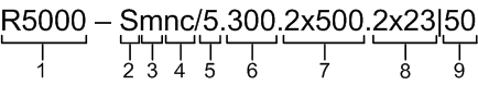
Structure items are described below
| Item | Description |
|---|---|
| 1 |
|
| 2 |
|
| 3 |
|
| 4 |
|
| 5 |
|
| 6 |
|
| 7 |
|
| 8 |
|
| 9 |
|
NOTE
Units may also be marked as “LITE” and “PRO”, where "PRO" - units that operate at greater distance and with higher performance. "LITE" refers to R5000-Smn and R5000-Lmn models, "PRO" - R5000-Mmx and R5000-Omx.
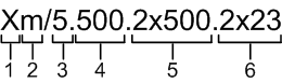
InfiLINK Evolution / InfiMAN Evolution

Structure items are described below
| Item | Description |
|---|---|
| 1 | Product family name:
|
| 2 | Frequency range:
|
| 3 |
|
| 4 | Antenna gain. Base Station Sectors:
Subscriber Terminals and PTP devices:
|
| 5 | Additional options:
|
InfiLINK XG / InfiLINK XG 1000
Structure items are described below
| Item | Description |
|---|---|
| 1 |
|
| 2 |
|
| 3 |
|
| 4 |
|
| 5 |
|
| 6 |
|
Quanta 5 / Quanta 6

Structure items are described below
| Item | Description |
|---|---|
| 1 | Product family name:
|
| 2 | Frequency range:
|
| 3 | Antenna gain:
|
| 4 | Additional options:
|
NOTE
Previously, device part numbers contained decimal number with the following structure:
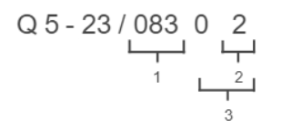
- Hardware version.
- Options:
- 0 - models with GigabitEthernet port and supporting 40 MHz channel width;
- 1 - models with GigabitEthernet port and supporting 50 and 56 MHz channel widths;
- 2 - models with Combo port GigabitEthernet/SFP and supporting 50 and 56 MHz channel widths.
Firmware version:
Quanta 70
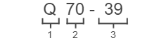
Structure items are described below
| Item | Description |
|---|---|
| 1 | Product family name:
|
| 2 | Frequency range:
|
| 3 |
|
MAC addresses and serial numbers mapping
Infinet Wireless devices have a one-to-one mapping between MAC addresses of network interfaces and serial numbers.
The MAC address has the structure 00:04:35:XX:YY:ZZ, where
- 00:04:35 – OUI (Original Unique Identifier) prefix identifying the manufacturer;
- XX:YY:ZZ – device ID.
InfiLINK 2x2, InfiLINK Evolution, InfiMAN 2x2 and InfiMAN Evolution families
Ethernet interface:
The device ID on the Ethernet interface is the device serial number in hexadecimal (HEX) format.
For example, to the device SN:76694 (HEX: 12b96) on eth0 would be assigned the MAC address 00:04:35:01:2b:96.
If a device has two Ethernet interfaces, then the device ID on the second Ethernet interface is formed by adding 10 to the first octet of the first Ethernet interface ID.
For example, to the device SN:76694 (HEX: 12b96) on eth1 would be assigned the MAC address 00:04:35:11:2b:96 (01 + 10 = 11).
Radio interface:
The device ID on the radio interface (rf) is formed by adding 10 to the first octet of the Ethernet interface ID. If a device has two Ethernet interfaces, then the device ID on the radio interface (rf) is formed by adding 10 to the first octet of the second Ethernet interface ID.
For example, on a device with one Ethernet interface SN:199383 (HEX: 30AD7), the MAC address of eth0 will be 00:04:35:03:0a:d7, rf5.0 - 00:04:35:13:0a:d7 (03 + 10 = 13).
To a device with two Ethernet interfaces SN: 199200 (HEX: 30A20) will be assigned the following MAC addresses:
- eth0 - 00:04:35:03:0a:20
- eth1 - 00:04:35:13:0a:20 (03 + 10 = 13)
- rf5.0 - 00:04:35:23:0a:20 (13 + 10 = 23)
NOTE
For H11 platform devices with one Ethernet interface, the ID on the radio interface is always 2+HEX.
SVI interface:
SVI interfaces use the MAC address of the first Ethernet interface, but with the prefix 02:04:35 instead of 00:04:35.
InfiLINK XG, InfiLINK XG 1000, Vector 4/5/6/70 families
The device ID on the management interface is the device serial number in hexadecimal (HEX) format.
For example, for SN:76694 (HEX: 12b96) - mgmt 00:04:35:01:2b:96.