Successfully pass the free certification exam at IW Academy and become an Infinet Certified Engineer.
Cable gland assembly for R5000-Mmx/Mmxb/Omx/Omxb/Qmxb models
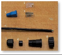
Required components:
- Unshielded RJ-45 connector
- Connector cover
- Shielded RJ-45 connector
- FTP Cat5e cable;
- Cable sealing nut
- Cable sealing grommet
- Cable gland case
- Cable gland nut
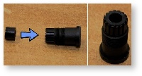
- Insert the sealing grommet (6) into the cable gland case (7) as shown on the picture
- Assemble the cable gland as shown on the picture by placing the cable gland nut (8) on the cable gland case (7)
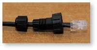
- Put the cable sealing nut (5) and the cable gland assembly (7,8) onto the cable as shown on the picture
- Crimp the unshielded RJ-45 connector (1) onto the cable using the crimping tool
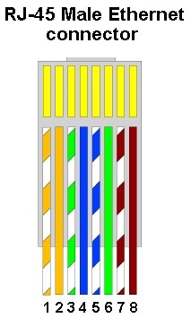
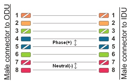
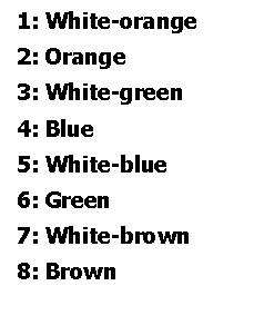
Pin-out scheme: T568B wiring standards
NOTE
The outside diameter value of the FTP Cat5e cable should not exceed 7 mm.
NOTE
Do not use the shielded RJ-45 connector on this end of the cable as it should be attached on the IDU end.
CAUTION
MAKE SURE THAT THE RJ-45 CONNECTOR IS WELL-CRIMPED. A LOOSE CONNECTOR CAN DAMAGE THE DEVICE. PLEASE NOTE THAT SUCH DAMAGE IS NOT COVERED BY THE WARRANTY.
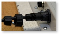
- Insert the cable gland assembly to the device socket
- Tighten the cable gland nut (8) until you hear a click by rotating it clockwise
- Tighten the cable sealing nut (5). Do not apply excessive force
Cable gland assembly for R5000-Smn/Lmn/Smnc models
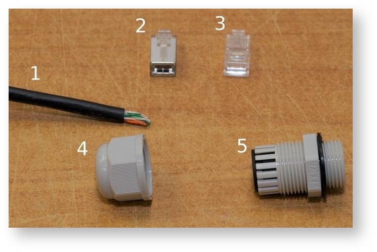
Required components:
- FTP Cat5e cable
- Shielded RJ-45 connector
- Unshielded RJ-45 connector
- Cable sealing nut
- Cable gland case
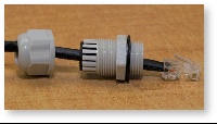
- Put the cable sealing nut (4) and the cable gland case (5) onto the cable as shown on the picture
- Crimp the unshielded RJ-45 connector (3) onto the cable using the crimping tool
NOTE
The outside diameter value of the FTP Cat5e cable should not exceed 7 mm.
NOTE
Do not use the shielded RJ-45 connector (2) on this end of the cable as it should be attached on the IDU end.
CAUTION
Make sure that the RJ-45 connector is well-crimped. A loose connector can damage the device. Please note that such damage is not covered by the warranty.
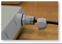
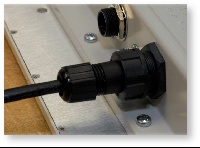
- Insert the connector into the socket until you hear a click
- Screw the cable gland case into the port and tighten it. Do not apply excessive force.
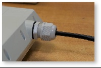
- Tighten the sealing nut (4). Do not apply excessive force.
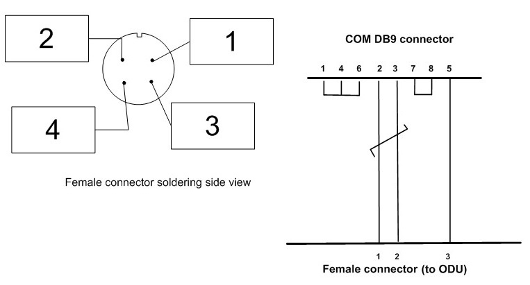
Console cable connector soldering scheme
NOTE
A properly assembled cable gland seales against humidity.