Successfully pass the free certification exam at IW Academy and become an Infinet Certified Engineer.
Lightning Protection Unit AUX-ODU-LPU-L

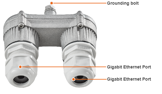
AUX-ODU-LPU-L is a bidirectional external outdoor lightning protection unit for Infinet Wireless systems designed to withstand the toughest conditions and protect the outdoor unit or the 3rd party networking equipment installed indoors from sudden power surges induced by lightning strikes. Despite the fact every Infinet wireless device has a built-in lightning protection. AUX-ODU-LPU-L, thanks to its superior GR-1089-grade protection, greatly reduces the risk of damage for the systems operating in harsh environments or difficult-to-reach locations. AUX-ODU-LPU-L is compatible with all Infinet Wireless devices.
NOTE
The device is not supplied by default and must be ordered separately.
| Parameter | Description | ||||||||
|---|---|---|---|---|---|---|---|---|---|
| Size and Weight |
| ||||||||
| Connectors and Interfaces |
| ||||||||
| Supported Ethernet Modes |
| ||||||||
| Water and Dust Protection |
| ||||||||
| Operating temperature range |
| ||||||||
| Ethernet pinout | Pin | 1 | 2 | 3 | 4 | 5 | 6 | 7 | 8 |
| Data pair | A+ | A- | B+ | C- | C+ | B- | D+ | D- | |
| Lightning Protection | In compliance with:
| ||||||||
Packing list

AUX-ODU-LPU-L is supplied with a worm clamp TORRO 40-60/9 C7 W4 DIN 3017. The clamp is made of stainless steel A4, width 9 mm, allows the installation on a mast with a diameter of 35 to 60 mm. In case of mast diameter more than 60 mm, a similar clamp (up to a 230 mm diameter) with a width of up to 12-13 mm can be used.
Lightning Protection Unit AUX-ODU-LPU-G

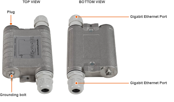
Optional indoor/outdoor Lightning Protection Unit for Infinet Wireless systems designed to withstand the toughest conditions and protect the outdoor or the indoor unit from sudden power surges induced by lightning strikes. It provides the same level of protection as AUX-ODU-INJ-G. AUX-ODU-LPU-G is compatible with all Infinet Wireless devices.
Despite the fact every Infinet Wireless unit has a built-in lightning protection, AUX-ODU-LPU-G, thanks to its superior GR-1089-grade protection, greatly reduces the risk of replacing damaged devices operating in harsh environments or difficult-to-reach locations.
NOTE
The device is not supplied by default and must be ordered separately.
| Parameter | Description | ||||||||
|---|---|---|---|---|---|---|---|---|---|
| Size and Weight |
| ||||||||
| Connectors and Interfaces |
| ||||||||
| Supported Ethernet Modes |
| ||||||||
| Water and Dust Protection |
| ||||||||
| Operating temperature range |
| ||||||||
| ETH IN and ETH OUT pin-out | Pin | 1 | 2 | 3 | 4 | 5 | 6 | 7 | 8 |
| Data pair | A+ | A- | B+ | C- | C+ | B- | D+ | D- | |
| Lightning Protection | In compliance with:
| ||||||||
Packing list

AUX-ODU-LPU-G is supplied with a worm clamp TORRO 40-60/9 C7 W4 DIN 3017 - 2 pcs. The clamp is made of stainless steel A4, width 9 mm, allows the installation on a mast with a diameter of 35 to 60 mm. In case of mast diameter more than 60 mm, a similar clamps (up to a 230 mm diameter) with a width of up to 12-13 mm can be used.
ANT-SYNC antenna
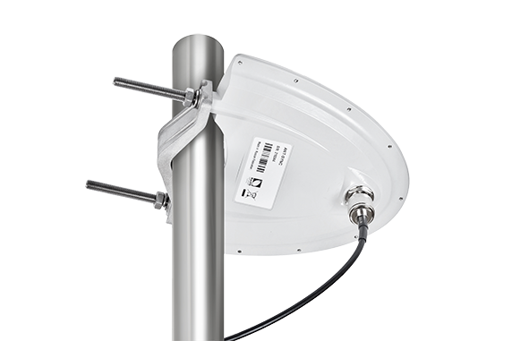
ANT-SYNC is an active GPS/GLONASS antenna designed to filter and amplify RF signals received from global navigation satellite systems (GNSS) and feed them to a GNSS receiver at InfiLINK XG, InfiLINK XG 1000 families models. GNSS receiver recovers timing and positioning data which is used to provide timing reference for TDD synchronization as well as to make device location information available for EMS and NMS systems via SNMP protocol.
As an active antenna, it protects the receiver from interference coming from co-located 3G/LTE BTSs, which would make GNSS signals irrecoverable otherwise. It requires DC power for normal operation, which is fed via the RF port, so it can only be used with compatible GNSS receivers such as those built into InfiLINK XG, InfiLINK XG 1000 families models.
TDD synchronization allows multiple co-located units to operate co-channel or use adjacent channels thus achieving frequency re-use and eliminate self interference. Because of GNSS-based timing reference, both intra- and inter-site synchronization can be supported.
| Parameter | Description |
|---|---|
| Antenna type |
|
Frequency bands |
|
| Input DC range |
|
| RF connector |
|
| Ingress protection |
|
| Size and weight |
|
| |
Relative humidity |
|
Installation
Installation must be performed by a professional installer only.
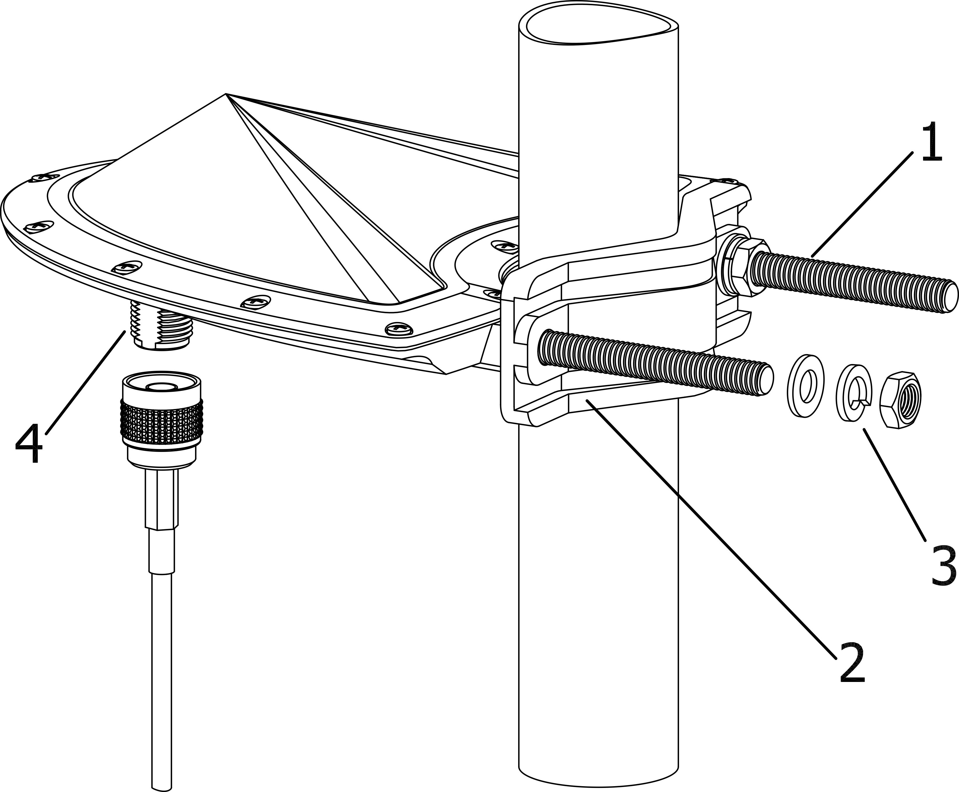
ANT-SYNC can be installed on a pole, using components kit from the delivery package. The recommended guidelines are given below:
- Screw the threaded studs (1) to the unit case.
- Tighten the device and the bracer (2) on the pole and fix them by the threaded studs (1) using the nuts and washers (3) as shown at the picture.
Typical pole diameter is 30 to 85 mm.
The N-type connector (4) is used to connect to the outdoor unit using the cable assembly from the delivery package.

