...
In the R5000 family devices, the modulation code scheme type is shown as a bitrate, in the InfiLINK XG family and InfiLINK XG 1000 families devices, MCS itself is displayed. In order to eliminate confusions, in the document below the MCS (modulation code scheme) index will be used. The correspondence between modulation and index is shown in the table below.
...
| Center | ||||||||||||||||||||||||||||||||||||||||||||||||||||||||||||
|---|---|---|---|---|---|---|---|---|---|---|---|---|---|---|---|---|---|---|---|---|---|---|---|---|---|---|---|---|---|---|---|---|---|---|---|---|---|---|---|---|---|---|---|---|---|---|---|---|---|---|---|---|---|---|---|---|---|---|---|---|
| ||||||||||||||||||||||||||||||||||||||||||||||||||||||||||||
Table of the correspondence between MCS index and modulation type in InfiLINK XG/InfiLINK XG 1000 family devices
| Center | ||||||||||||||||||||||||
|---|---|---|---|---|---|---|---|---|---|---|---|---|---|---|---|---|---|---|---|---|---|---|---|---|
|
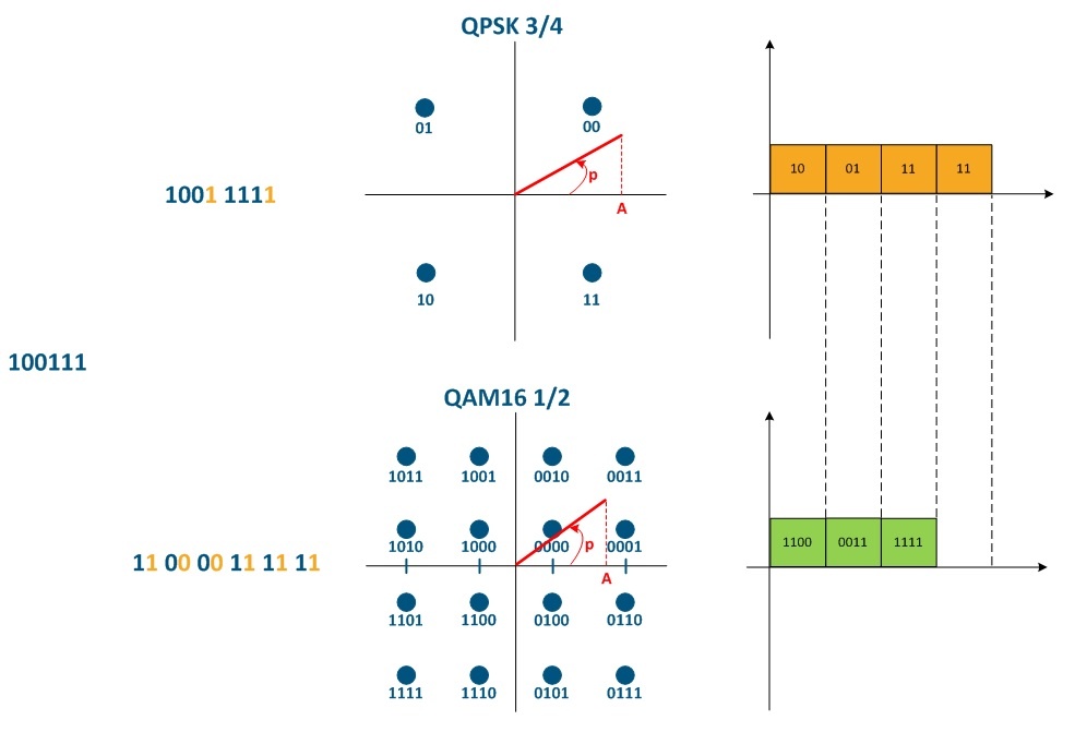
Figure 1 - The impact of the modulation code scheme on the communication channel throughput
...
| Anchor | ||||
|---|---|---|---|---|
|
To explain the radio frame size effect on the link quality parameters, let's look at the connection of two devices (InfiLINK XG/InfiLINK XG 1000 or R5000 with TDMA firmware). The transmitting information mechanism in the radio medium is presented below (see Figure 4). For detailed description of the data transfer mechanisms for TDMA and Polling see TDMA and Polling: Application features. A radio frame is a time period within which a subscriber unit terminal is serviced by a sector. During one radio frame, data is exchanged between two devices in the downstream and upstream.
...
Figure 4 - The transmitting data mechanism for TDMA and TDD
...
Distance range
The "Maximum distance" parameter affects the guard interval value (see Figure 4), and also the efficiency of using the link throughput. In addition, the actual farness of the subscriber station terminal affects the radio signal propagation time in the media.
...
Let's add to the picture from the "Radioframe Radio frame size", section two more subscriber devices (see Figure 5).
The transmission waiting time is proportional to the number of subscriber devices, since a time interval equal to the radioframe radio frame size is allocated for data exchange with each station. Thus, the delay value depends on the number of active subscribers.
...
Figure 5 - The transmitting data mechanism for TDMA with three subscriber deviceterminals
Propriate parameters set
Greenfield
...
The Greenfield option is activated on both Master and Slave devices and is responsible for optimization of service information transmitted via the radio link. Optimization significantly reduces the amount of service information and improve performance by 10-15% due to an increase of useful data share in the radio frame.
VBR
...
The VBR option (variable bitrate) can be configured on the slave device and allows to increase efficiency of the service data transmission. With the VBR option disabled, the Sync message service fields are transmitted using a minimum modulation code scheme. When VBR is enabled, Sync fields will be transmitted on the modulation code scheme higher then the minimal, if possible. This allows to transmit the sync sequence faster, reduces the share of service messages in the total transmission time and increases the link performance
...