...
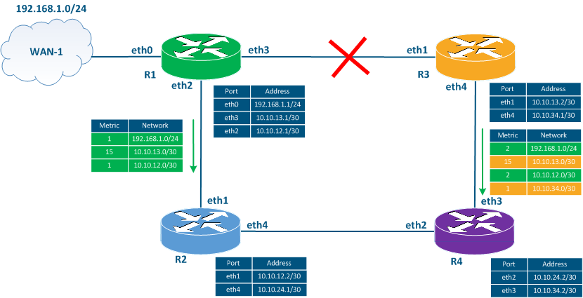
- Step 1: the interfaces eth3 of R1 and eth1 of R3 will become down.
- Step 2: R1 and R3 will set the metric's value to 16 for the route towards network 10.10.13.0/30 in the RIB.
- Step 3: according to the update timer's expiration, routers R1 and R3 will generate a service message including the known routing information. This message includes the route to the unreachable network with the metric 15.
- Step 4: routers R2 and R4 receive the service messages from R1 and R3, increment the metric value, and add the route to the RIB. The RIB of the routers R2 and R4 already has a route to the 10.10.13.0/30 network with the metric 2, but since the sources of the new routes with the worst metric are the same routers, then the route in the RIB will be replaced with a route with the metric 16. Thus, all the routers in the network will receive information about the link's unavailability.
| Center |
|---|
Figure 3b - The example Transmission of the service messages distribution in case of link failsfailure |
Time The time during which the updated information is distributed depends on the the size of the network size and on the update timer's value. As the maximum network size is 16 hops , and the update timer by default is 30 seconds, then in the worst scenario, the distribution information time about the link's unavailability will be transmitted in 15 * 30 = 450 seconds.
...
A router is out of order
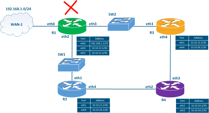
Let's add two switches SW1 and SW2 to the scheme in (Figure 3c) and assume the failure of that router R1 has failed.
If router R1 fails, it does not have time to send a the routing information update about its unavailable status to routers R2 and R3. In addition, R2 and R3 won't be informed that R1 is unavailable because they are directly connected to switches SW1 and SW2 without which don't support RIP support. In this case, the network other routers will assume that R1 available during the timeout timer and will use the routes associated with R1. Particularly, the routes to networks 10.10.12.0/30, 10.10.13.0/30 and 192.168.1.0/24 will be valid in the routing table tables of all the routers.
| Center |
|---|
Figure 3c - The example Transmission of the service messages distribution messaged in case of router failsfailure |
False routes
...
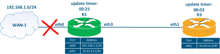
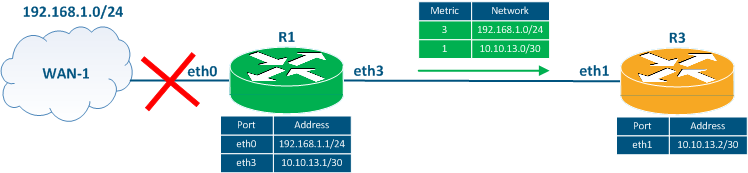
Let's simplify the scheme, leaving two routers R1 and R3 (Figure 4a). We will assume that the routers have exchanged routing information and the device's routing tables are up to date.
...
| Center | ||||||||||||||||||||||||||||||||||||
|---|---|---|---|---|---|---|---|---|---|---|---|---|---|---|---|---|---|---|---|---|---|---|---|---|---|---|---|---|---|---|---|---|---|---|---|---|
Figure 4b - Route R1 - WAN-1 fails
| ||||||||||||||||||||||||||||||||||||
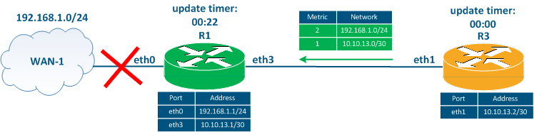
3 Three seconds later after the R1 - WAN-1 link failshas failed, the R3's update timer expires, so R3 sends a routing update to R1 (Figure 4c). This update contains information about the 10.10.13.0/30 and 192.168.1.0/24 networks. Router R1 adds a route to the 192.168.1.0/24 network to the RIB, because its metric is better than the route that has already been added to the RIB.
A routing loop is formed, each router, passing traffic to the 192.168.1.0/24 network, refers to another router. ThusThus, the traffic will be transmitted by between the routers to each other until the TTL expires. In addition to the routing loop generation, both routes are false as a the connection to with the network 192.168.1.0/24 is lost.
| Center | ||||||||||||||||||||||||||||||||||||
|---|---|---|---|---|---|---|---|---|---|---|---|---|---|---|---|---|---|---|---|---|---|---|---|---|---|---|---|---|---|---|---|---|---|---|---|---|
Figure 4c - Service message distribution with routing information by router R3
| ||||||||||||||||||||||||||||||||||||
The fails route usage false routes will continue until the timeout timer expires on R3. After that, after that R3 will set the metric value for this route to 16. In the next routing information distribution, router R1 will send route routing information to router R3 with information about the 10.10.13.0/30 and 192.168.1.0/24 networks (Figure 4d). Since the metric for the route to 192.168.1.0/24 is 3, and less than 16, R3 will add a false route to the RIB, incrementing the metric value.
The false route exchange will continue until the metric value reaches the invalid value 16. With the default settings, this will happen 36 minutes later after the occurrence of the link failure between R1 and WAN-1.
| Center | ||||||||||||||||||||||||||||||||||||
|---|---|---|---|---|---|---|---|---|---|---|---|---|---|---|---|---|---|---|---|---|---|---|---|---|---|---|---|---|---|---|---|---|---|---|---|---|
Figure 4d - Service message distribution with routing information by router R1
| ||||||||||||||||||||||||||||||||||||
To avoid the appearance of the false routes appearance in the RIP protocol, the following mechanisms are used:
- split-horizonthorizon: мrouters the routers do not distribute any routing information updates to those routers which are the sources of this the information. In the example above (Figure 4d), router R3 will not include information about the route to the 192.168.1.0/24 network in the message for router R1, since R1 is the source of this information. This will allow to avoid the described situation, but will not work effectively in a scheme with a large number of routers. In the scheme with four routers (Figure 1) when the link with WAN-1 is out of order, then routers R2 and R3 will not transmit information about the route to the 192.168.1.0/24 network for R1. However, this route is also in the router R4's RIB and it will be included in the periodic distribution of the routing information, which will lead to the appearance of a false route appearance.
- poison-reverse: this mechanism implies immediate distribution of the updates about unavailable routes without waiting for the update timer expiration. An unreachable route is sent with a metric of 15, it incrementing by so each router will increment the metric and lead to an unavailable route in the RIB. The mechanism has a disadvantage, since the routing information distribution about an unavailable route requires a certain time, during which a message with old routing information can be sent , where and include the unavailable route will be marked as available.
- garbage-timer: the device does not accept updates for routes marked as unavailable before the garbage-timer expires.
The listed mechanisms make it possible to adapt the RIP for the modern networks, since the false routes existence for 36 minutes or a protocol convergence time for of 450 seconds is unacceptable for many services.
...
RIP has the following features:
- the operation operational algorithm used in by RIP is easy to understand and to configure;
- RIP is a standard protocol and can be implemented in using devices from different network devices manufacturers;
- false routes may appear in the protocol: this disadvantage was eliminated by adding additional functions to the protocol, but this make makes the protocol's operation and implementation more complicated;
- there is a network size limitation where the RIP algorithm can be usedof 16 hops;
- it takes a long time of for the network adaptation to adapt to changes.
Additional materials
...