| Include Page | ||||
|---|---|---|---|---|
|
| Hide_comments |
|---|
It is recommended to have two teams prepared for alignment procedure, each team with at least two installers: one should notisy the signal values and communicate with the remote side, the other should make the adjustments with the device. Using the azimuth and elevation values computed by the link planning tool, each team will roughly position the antenna (in each location) to detect the opposite system signal
...
.
...
After the initial approximate alignment (link up), the antenna with the lowest gain should be locked into position.
Both teams will connect to the unit, and from the web GUI will:
...
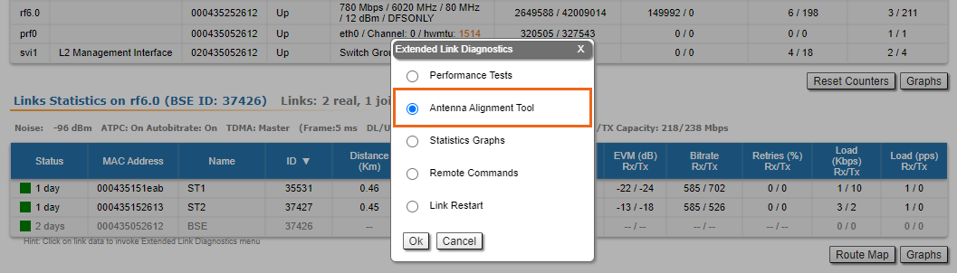
should use the Antenna Alignment Tool in the Device Status section of the web GUI.
| Center |
|---|
|
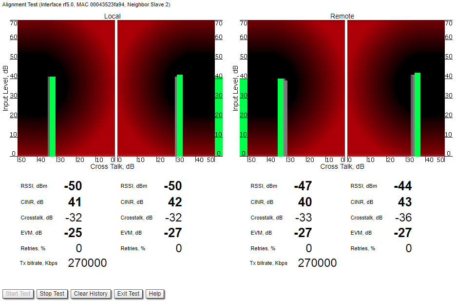
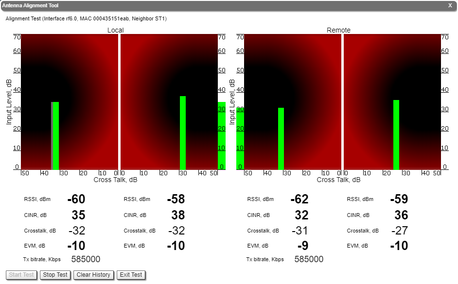
The team at the antenna which has the highest gain will click on the "Start Test" button and start to change the azimuth slowly while watching the signal indicators
...
- RSSI - indicates the power level of the received radio signal, optimal parameter value -60 ... -40 dBm.
- CINR - input signal level to noise + interference indicator, >=28 dB.
- Crosstalk - indicates how much vertically and horizontally polarized signals influence each other, >20 dB in absolute value.
- Error Vector Magnitude (EVM) - indicator of the measured input signal quality (it should be as high as possible in absolute value, the recommended level is not less than 21 dB in absolute value. Some old firmware had EVM value positive, but most the firmware has negative value, so for the troubleshooting, evaluate the absolute EVM value) .
- Retries - percentage of transmit packet retries (measured in %), <5.
- Tx bitrate - displays the current bitrate for the remote and local units (measured in Kbps).
| Center |
|---|
|
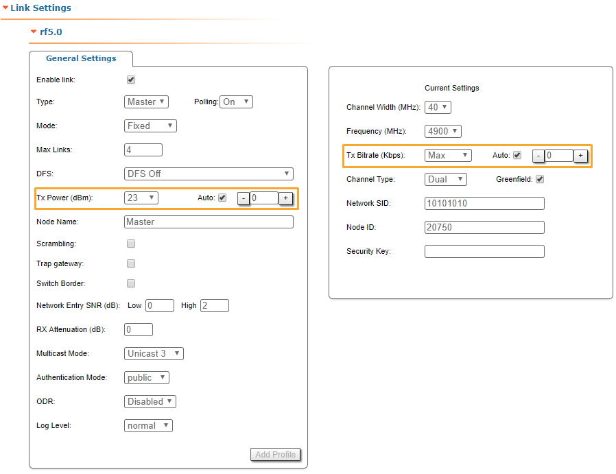
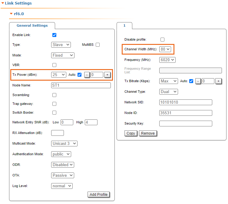
As soon as the antennas have been precisely alignment, set the "auto" option for Tx power and bitrate at both units, bearing in mind the EIRP limitations.
...
- Decrease/increase the Tx power level (keeping the auto option checked) to have the SNR at around 25 dB and the RSSI at around -55 dBm.
- Decrease the bandwidth to lower the noise and to increase the SNR to above 20 dB.
| Center |
|---|
|
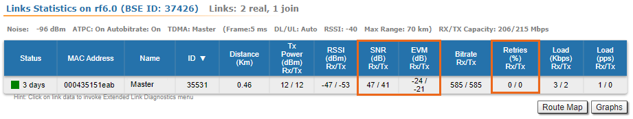
Wireless link statistics
- Let's check the link parameters (for the correct link model according to the link distance, with an optimal antennas alignment, clear working frequency, and Clear-Line-of Sight, the values displayed must be the optimal ones for that particular link). Go to the Device Status section and in the Link Statistics, check the Level Rx/Tx and Retries Rx/Tx:
- Retries Rx/Tx: maximum 5 %.Level
- EVM Rx/Tx: not less than 21 dB in absolute value.
- SNR Rx/Tx: minimum 20 not less than 27 dB.
| Center |
|---|
|

| Note | ||
|---|---|---|
| ||
If the two conditions above are not met, decrease the bandwidth from 40 MHz to 20 MHz, or even to 10 MHz, to lower the noise and to increase the SNR to above 20 dB. |
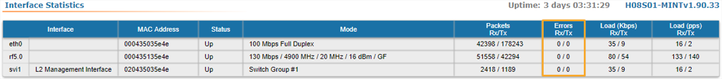
Interface statistics
- Let's check the number of Rx/Tx errors for the Ethernet and Radio interfaces are close to “0”, which is the case for an optimal link establishment (no traffic is generated through the wireless link at this stage).
- Go to the Device Status section and in the Interface Statistics for eth0 and rf5.0 interfaces, check the Errors Rx/Tx.
| Center |
|---|
|
If these conditions are met and the maximum bitrate is reached, the wireless connection quality is good. Otherwise, use the diagnostic tools described in the Troubleshooting article.