...
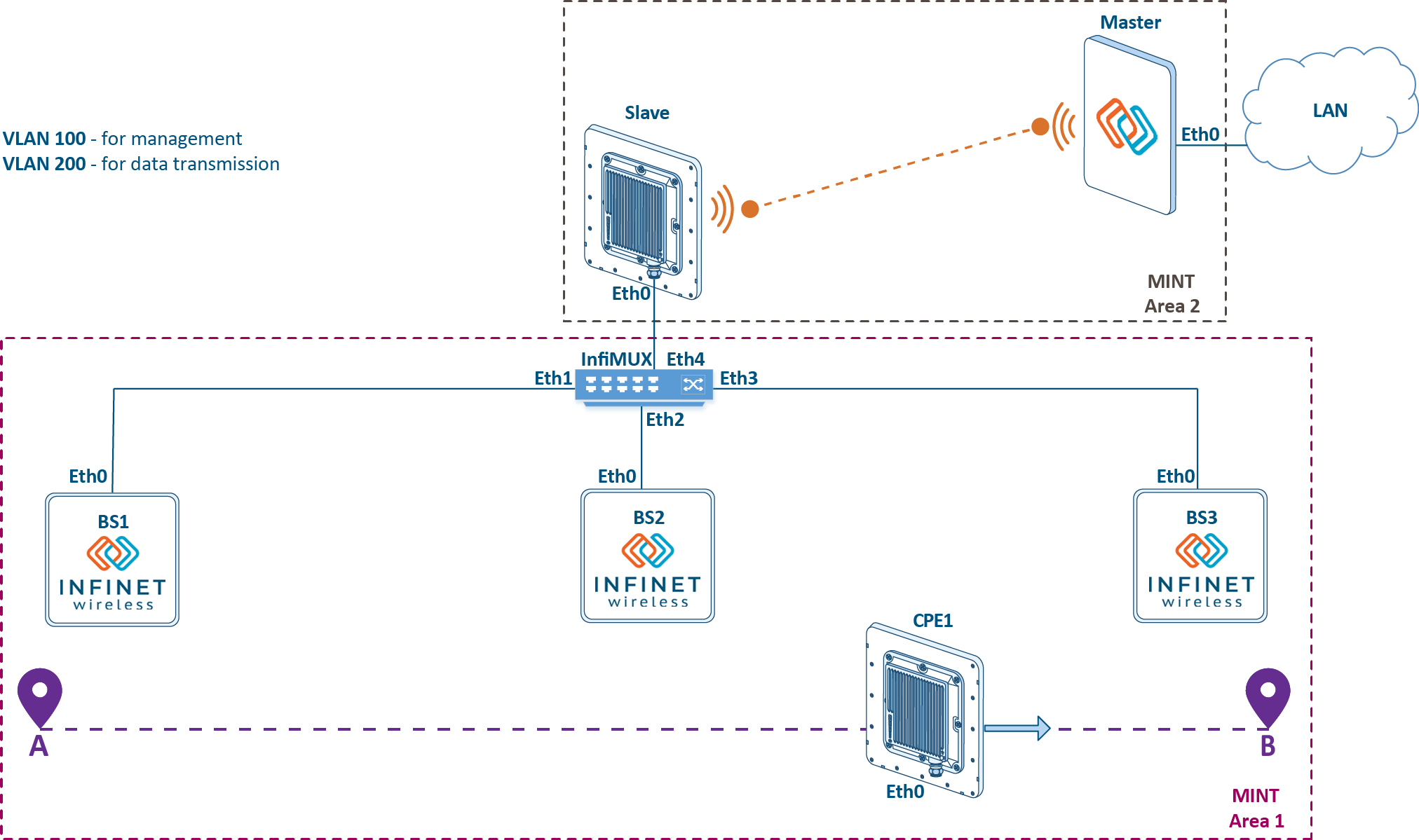
- The base stations BS1, BS2 and BS3 are installed along the area perimeter, forming the backbone radio network. Single-sector base station configurations are used, i.e. each BS has one sector. Non-overlapping frequency channels are configured on the base station sectors.
- A mobile object moves within the backbone radio network from point A to point B. A subscriber station CPE1 is installed on a mobile object. Depending on the requirements for the connection reliability, there are two implementation options: the installation of one subscriber set with a circular radiation pattern, or the installation of two subscriber sets on each moving object. While moving CPE1 installed at the object can establish a radio link with devices of the backbone radio network BS1, BS2 and BS3.
- The aggregation node is joined with BS2, there InfiMUX is installed. All BSs sectors are connected to InfiMUX, which joins radio backbone network devices into a single MINT area.
- The aggregation node and enterprise LAN are connected via the Master-Slave backbone link.
- The Global function is enabled on CPE1 and InfiMUX.
- "Mode nomadic" is set on the backbone radio network devices and CPE1, "mode fixed" - on the Master and Slave devices. Depending on the project specifics, other mode values may be set.
- For device management, VLAN 100 is dedicated, which is associated with the 192.168.100.0/24 subnet.
- VLAN 200 is used for data transmission service.
| Center |
|---|
Figure 1 - Example of a project with mobile objects |

...