| Table of Contents |
|---|
| Warning | ||
|---|---|---|
| ||
Configurations from the scenarios below are examples that demonstrate the potential capabilities of the InfiNet Wireless devices. The configurations may vary depending on the model and firmware version. We do not recommend copying this solutions to the hardware without checking. |
Description
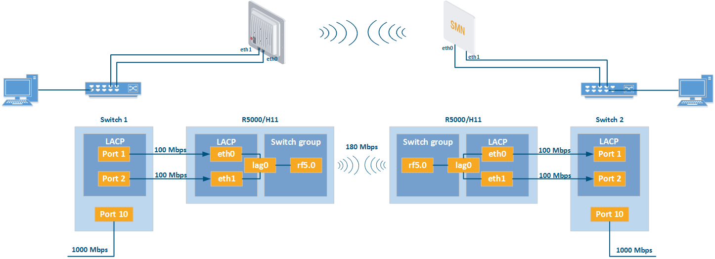
The maximum throughput of a single port is limited by the standard 100Base-TX. The radio module throughput can be higher depending on the MCS and the channel width. The maximum achievable throughput of the InfiLINK 2x2 LITE and InfiMAN 2x2 CPE families units is up to 180 Mbps of the bi-directional aggregated stream. It is not possible to use the maximum throughput of the radio channel in one direction through one 100Base-TX port. However, the ports aggregation into one LAG allows achieving the maximum throughput in one direction.
| Center |
|---|
PtP scheme |
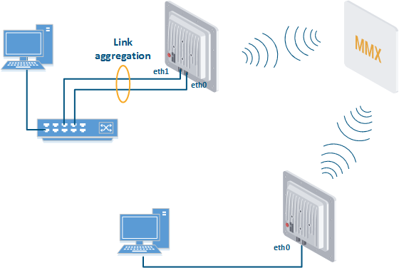
This scenario can be also used in "point-to-multipoint" topologies.
| Center |
|---|
PtMP scheme |
Configuration via GUIAnchor GUILAG GUILAG
| GUILAG | |
| GUILAG |
Create a LAG interface.
Center 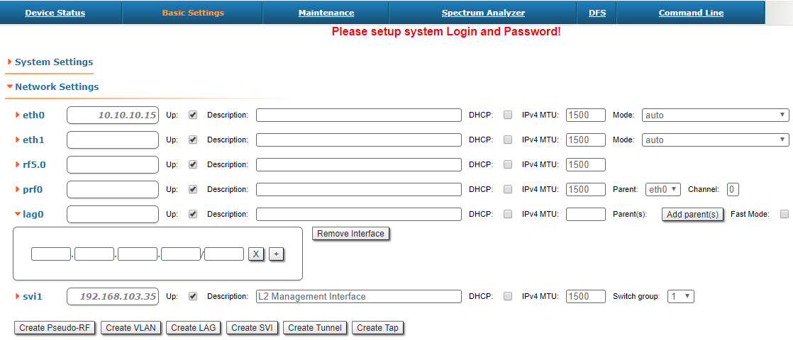
Add ports.
Center 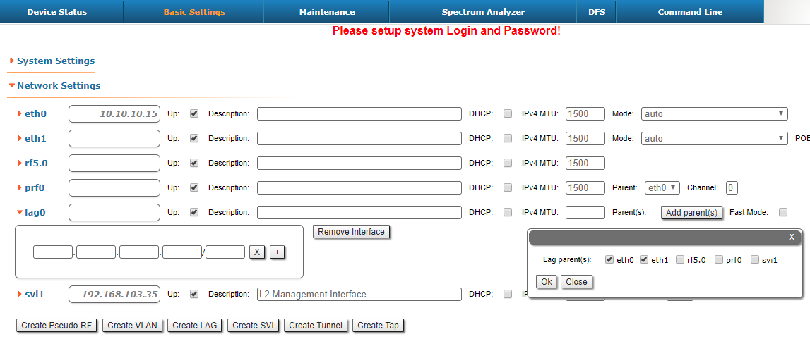
Select LACP (Standard or Fast mode). "Standard" LACP fully complies with the standard IEEE 802.3ad. “Fast” LACP uses only with InfiNet Wireless devices and increases efficiency and performance compared "Standart" mode.
Warning title CAUTION The "Fast" mode is a proprietary extension of the LACP protocol. Compatibility of this mode is guaranteed only with devices that support MINT protocol.
Center 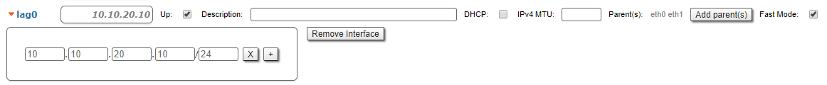
- Assign management IP for LAG interface or SVI (optionally).
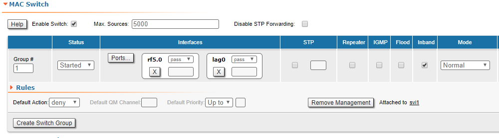
- Configure switch group.
| Center |
|---|
|
Configuration via CLI
"lag" command and its parameters description is given in the section "lag command (Link Aggregation )".
Configuration Example
Configuration via CLI:
Create LAG interface, add eth0 and eth1 interfaces to it.
Code Block language text theme Emacs title LAG Creation lag 0 port eth0 eth1 ifc lag0 up
Assign management IP for a LAG interface or SVI (optionally).
Warning title CAUTION If you associate a management IP address with a LAG interface, you must first assign the IP address to the interface and then make the interface active.
Code Block language text theme Emacs title Creating Managment ifc lag0 10.10.10.1/24
Configure switch group.
Code Block language text theme Emacs title Creating Managment switch group 1 add 2 rf5.0 lag0 switch group 1 start