| Include Page | ||||
|---|---|---|---|---|
|
| Hide_comments |
|---|
...
- An unique numeric identifier (1-40954999) for each group
- Two or more local network interfaces (ethX, rfX, tunX, etc) and a set of rules (filters) which allow placing different types of traffic into different switching groups
- Each node can have several switching groups. The same interfaces or group of interfaces can be used in several groups simultaneously
- Switching groups are activated on different nodes of the MINT network. The nodes that have the same switching group identifier in their configurations represent a "switching zone"
- "Switching zone" exists only within the MINT network segment.
...
If you enable the trunk group at the BS side to transmit several VLAN-flows to several directions, then at the CPE side, you should use the "In-Trunk" option to specify the group number of the trunk group that includes the required switching group.
| Center | |||||
|---|---|---|---|---|---|
|
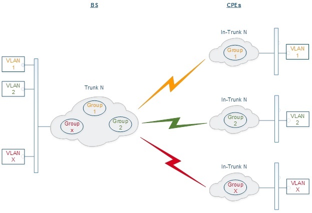
Trunk During data transmission through a wired switch, the group number is automatically converted to the 802.1q VLAN tag, and vice versa, when a packet is received through the wired switch, the VLAN tag is converted to the corresponding group number.
Trunk groups may also be used to solve the task of connecting several VLAN segments.Special
| Center | |||||
|---|---|---|---|---|---|
|
Special rules on interfaces allow flexible manipulations with VLAN ID tags: deleting, assigning and re-assigning (please consult the information provided in WANFleX OS User Manual).
...
In the "MAC Switch Group parameters" section, you can view the Switch Groups and Rules that are already created, including the management switch group; you can change the parameters for these Switch Groups, delete them by clicking the «Remove Group» button or create new ones by clicking the «Create Switch Group» button. The same operations are available for the switching rules: add a new rule within a switch group by clicking the «Add Rule» button (located within sub-menu "Rules" of this group) or delete an existing rule by clicking the «Remove Rule» button.
| Center | |||||
|---|---|---|---|---|---|
|
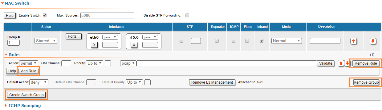
General options in this section:
...
clicking the «Remove Rule» button.
| Center | |||||
|---|---|---|---|---|---|
|
General options in this section:
- Enable Switch - enables/disables global switch operation
- Max Sources - sets the maximum allowed number of records in the switch MAC address table. The default number of records is 5000.
- STP MINT mode - enables/disables the STP MINT mode. STP MINT mode is used to exclude the wired switches with the enabled STP protocol influence on the network operation. The mode blocks the BPDU frames of the STP protocol configured on wired switches so that the switch cannot detect the loop and block its ports. STP MINT mode in conjunction with the RSTP protocol enabled in the Infinet devices allows to break the loop and support the PRF protocol functioning that operates through the wired segment.
| Warning | ||
|---|---|---|
| ||
Disabling the switch in the absence of routing settings can lead to termination of packet transmitting through the device. |
- «Remove L3 Management» Management - by clicking this button you can delete the "sviX" interface, which is available in the default configuration, for the unit management
- «Create L3 Management» Management - by clicking this button you can add an "sviX" interface for the unit management via Web interface (please consult the configuration examples presented in chapter "Configuration scenarios").
«Switch "Switch Group configuration» configuration" section:
| Center | |||||||||||||||||||||||||||||||||
|---|---|---|---|---|---|---|---|---|---|---|---|---|---|---|---|---|---|---|---|---|---|---|---|---|---|---|---|---|---|---|---|---|---|
|
...
In this section you can set the IGMP-parameters for the groups for which support of IGMP snooping is enabled (the IGMP check box is marked for these groups in the "MAC Switch" section).
| Center | |||||
|---|---|---|---|---|---|
|
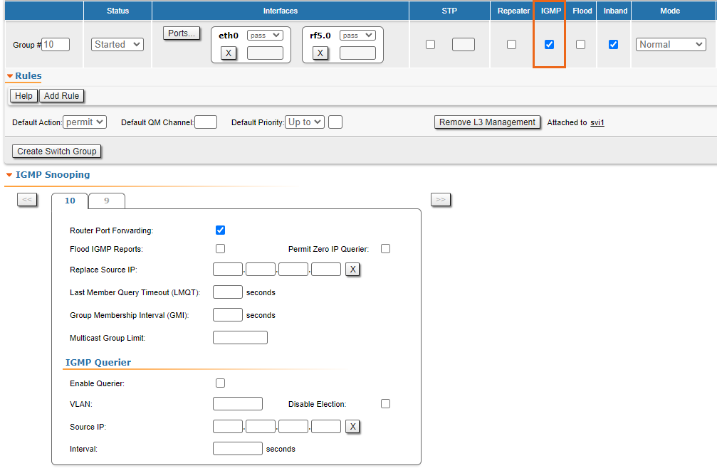
IGMP Snooping is a multicast constraining mechanism that runs on Layer 2 devices to manage and control multicast groups. By listening to and analyzing IGMP messages, the device running IGMP Snooping establishes mappings between ports and multicast MAC addresses and forwards multicast data based on these mappings.
...