| Include Page | ||||
|---|---|---|---|---|
|
| Hide_comments |
|---|
| Table of Contents | ||||
|---|---|---|---|---|
|
...
The purpose of this document is to present information about the features and applicability of the the TDMA and and Polling technologies technologies for MIMO units of the R5000 product family.
All MIMO devices of the R5000 product family could be used with with Polling technology technology (by default), or with TDMA technology. Polling firmware version described as “MINT”, TDMA firmware as “TDMA”. Both software versions are available on the official InfiNet Wireless FTP server:ftp https://ftp.infinet.ru/pub/Firmware/.
Firmware upgrade fully replaces previous firmware, configuration kept with no modifications after upgrade. Upgrade could be done during any free from service provision technological cycle with short-time wireless network link interruption (device reboot is required for firmware upgrade).
| Note | ||
|---|---|---|
| ||
Software upgrade process from firmware “MINT” to “TDMA” is described in details here: Upgrade How to upgrade from MINT to TDMA. |
Necessary description of 802.11x protocol features
...
Polling technology
Algorithm CSMA/CA
Polling technology technology uses the algorithm CSMA/CA, described by 802.11x standards set, as the method for media access.
CSMA/CA CA was created in order to resolve collisions issue, which happened with multiple access in PtMP topologies.
...
Proper operation of CSMA/CA algorithm requires the important factor accomplishment: all CPEs should be able to listen directly each other’s signals. In case, the radio radiation from some CPEs could not be detected by the other CPEs (for example, narrow beam antennas with high gain in the limited radiation sector were used) – then different subscriber terminals would transmit simultaneously, thus causing collision on BS receiving side.
...
The advantage of CSMA/CA algorithm is the following: the transmission of some certain size packet requires the same amount of time, which requires for data propagation in the air. Such advantage is applicable for for Polling technology technology too.
| Center | |||||
|---|---|---|---|---|---|
|
...
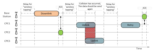
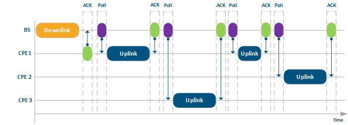
Once of the collision avoidance solutions is is Polling – – strict control of the transmission from all subscriber terminals from the base station side by using special admission for CPE to start Uplink transmission. BS sends the special service packets “markers” (poll), which admits CPE to start Uplink transmission. The transmission won’t start until the CPE receives “marker” from the BS, which of course leads to latency increase.
...
| Center | |||||
|---|---|---|---|---|---|
|
Acknowledgement and retries process brings more reliability in general and decreases the amount of lost data. At the same time, such operation could create a problem in PtMP topology, because one “bad” subscriber with a lot of interference increase latency for all subscriber terminals, which don’t have any interference instead and could sent more traffic. In result, total throughput of the base station significantly depends from the existence of such “bad” subscriber terminals.
| Note | ||
|---|---|---|
| ||
Configuration of units in the marker access networks (Polling technology) should be done in accordance with recommendations from the documentation: Link Settings |
TDMA technology
Another way to prevent collisions is to use use TDMA technology technology.
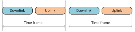
TDMA splits every communication session into two time-frame streams from the unit (for example, from BS to CPE) and, in the backward direction, to the unit. Each time frame has the same size, which is determined by the transmission time (for example, 10 ms), and also depends on the channel band size, modulation scheme and some other parameters.
...
| Center | |||||
|---|---|---|---|---|---|
|
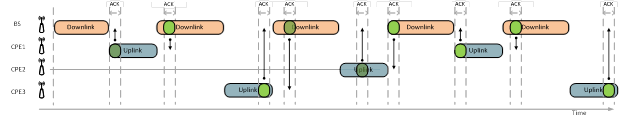
Unlike of of Polling technology technology, TDMA provides provides synchronization between the base station and subscriber terminals.
...
| Center | |||||
|---|---|---|---|---|---|
|
...
|
TDMA uses continuous byte stream transmission instead of packet transmission used in Polling technology. This is done specially in order to fully utilize limited time devoted for transmission. TDMA byte stream is divided into multiple portions, but these portions are cut according to time size, not by length. Therefore, since total size of time frame is fixed, then in case of insufficient data to fill time frame completely – the unloaded part of time frame would be sent in vain. Usage of shorter time frames size helps to amend such drawback and at the same time decrease latency, however the short time frame size leads to decrease proportion of customer traffic payload within the time frame and decrease of maximum throughput.
...
| Center | |||||
|---|---|---|---|---|---|
|
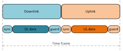
Sync Sync – service information, required to maintain synchronization of the wireless link and ARQ mechanism operations. It has a fixed duration, which depends only on the current channel width. Sync doesn’t depend from the time frame size.
Guard – – protective interval to prevent collisions occurrence. The duration of the protective interval depends only on the distance between units (approximately 3 ms for µs for 1 km).
The total volume of the service information (Sync + Guard) more or less is constant for the selected channel width and distance and doesn’t depend on the time frame duration. Therefore, the change of the time frame duration leads only to change of customer payload data size (Downlink Data / Uplink Data).
...
Network hookup process
TDMA hookup hookup to network process differs from from Polling. With TDMA subscriber terminal does not transmit anything until finally connects to the base station. During search for the base station stage, subscriber terminal only scans all frequencies, listens signals from the base station – creates maps of potential candidates to connect to. Afterwards, the subscriber terminal waits to receive a special signal from the selected base station sector to send the connection request. Such signal is being transmitted periodically by each base station and allows connection of new subscriber terminal, without causing interference to already connected subscriber terminals. Moreover, with TDMA technology all such hookup process is being performed rapidly than the same process with with Polling technology technology.
TDMA time frame structure in PtMP topology
...
| Center | |||||||||||||||||
|---|---|---|---|---|---|---|---|---|---|---|---|---|---|---|---|---|---|
|
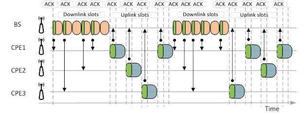
In such circumstance, system can send and receive data from several CPEs during one time frame. Such subslots usage significantly decreases latency in highly loaded by subscribers PtMP, however throughput of the whole PtMP decreases too due to higher amount of the service data used and decrease of payload data size. The system use only one subslot in each direction, then average latency for the subscribers (Round-Trip, in case all subscribers are equally active) would equals number of subscriber stations multiple on time frame size and index "2.5". Usage of several subslots decreases latency proportionally to number of subslots. Meanwhile, the more number of subslots is used, the less would be the part of customer payload within the Uplink time frame. Hence with ratio DL/UL 50%, throughput in Uplink part, would be much less than Downlink. It stands to reason Downlink is dedicated only for transmission of data by the base station, however Uplink is shared among all subscriber stations – consequentially, the more number of subscriber stations, the less amount of Uplink is being provided to each subscriber terminal. Accordingly, it is required to ensure symmetrical sector load – then DL/UL ratio should be lower (for example, 45%). Moreover, DL/UL ratio more than 60% with relatively big number of connected subscriber terminals, does not result in increase of throughput Downlink, because decrease of subslots number drastically increases the latency (whereas throughput decrease and each subscriber unit experience output queue size increase), in consequence, ARQ mechanism does not function correctly, because acknowledgement of data requires a lot of time.
| Note | ||
|---|---|---|
| ||
Configuration of units in the time division networks (TDMA technology) should be done according to the recommendations specified in the documentation: Link Settings |
When it is recommended to use TDMA
...
| Center | |||||
|---|---|---|---|---|---|
|
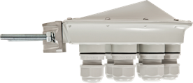
The external synchronization source allows time synchronization (every second start) on several devices (up to 7) with an accuracy less than one microsecond in such manner, that all connected devices would turn on the transmitters at the same moment of time. By doing this way – mutual interference of the neighboring sectors will be fully excluded. In either case single transmitting device by its powerful signal could interferes the other device to receive weak signals coming from the subscriber terminals. Synchronization unit (AUX-ODU-SYNC) has a built-in GPS/GLONASS receiver, and could be even used out of satellite access zone (for example, in the building). In this case, built-in clock generator works out ubiquitous clock pulse to all connected devices. However, it is required to eliminate inter-site interference (two independent base stations, located at some distance from each other), receiving of satellite signal is obligatory. This allows to use GNSS satellite signal as ubiquitous clock pulse.
...
Example 2: BS has 4 sectors with Polling
| Center |
|---|
 |
“Bad” subscriber issue solution
...
One of the solutions to solve the “bad” subscriber problem is to use use TDMA technology technology. Even in case of high level of retries experiencing by one of subscribers, this particular subscriber will receive new (dedicated) time frame. Herewith the effectivity of other subscriber terminals throughput would be left intact, and consequentially the throughput of the whole wireless network won’t decrease.
...
| Center | |||||
|---|---|---|---|---|---|
|
...
|
In case TDMA technology application, packets latency is stable and almost does not depends on the channel load (retries are not present). In case of retries, latency would increase because each retried packet would be sent in a new time frame and would occupy the same time as the original packet. However, this delay will not affect service of the subscribers who have no problems with data transmission.
...
High quality service guarantee could be achieved only with TDMA technology.
| Center |
|---|
|
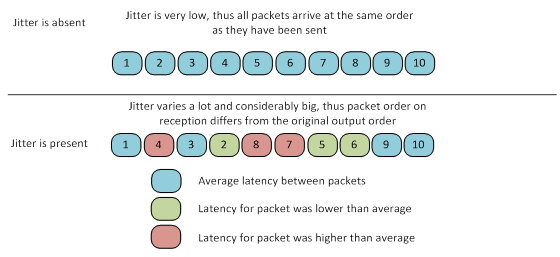
With With Polling technology technology the implementation of the throughput of the wireless network in PtMP topology, most likely would be even higher than the throughput with with TDMA technology technology, however jitter would be small and stable only with with TDMA technology technology. Unstable jitter leads to significant degradation of real time application services, especially for VoIP.
Operation in severe conditions: nLoS, over the water links
TDMA technology technology ensures a stable wireless communication channels even in the absence or limitation of clear Line-of-Sight zone (buildings in city, forest, over the water links). Such conditions could cause the creation of multiple reflected signals from the obstacles. One part of the reflected signals will scatter, another part will reach receiving device using longer path or will return to transceiver with some delay (at long links the delay could be several dozens of seconds). In such way, the reflected signal can mix with wanted signal (for example, with acknowledgement packet ACK, which should be sent as fast as possible after data receiving) and cause interference or signal distortion.
TDMA solves solves such problem by the introduction of a protective interval (guard) at the end of each frame, which admits to delay start of transmission until all reflected signal fade. The guard interval duration can be changed in configuration of the base station.
...
As the result, it is recommended to use system with PtMP topology in narrow bands (5 and 10 MHz) with Polling technology. TDMA technology could be used in narrow bands only in case the total volume of traffic is relatively small, but SLA requirements are very strict, for example, the wireless links are devoted for VoIP traffic transport.
Conclusion
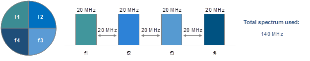
TDMA technology technology allows to create multisector base station with a high density of available frequencies usage. In other words, current available frequency resource could be utilized more effectively in case of migration to to TDMA technology technology. Moreover, TDMA provides provides tool to ensure stability under near LoS conditions and for over the water links.
However, TDMA only only elaborates with with Polling technology technology without replacing it. In case of strong interference or in narrow bands, Polling is the recommended technology to rely on.
Both technologies ensure maximum effective operation of InfiNet Wireless equipment in various environments and projects.
Links
See also:
- Upgrade from Polling to TDMA.
- Radio link settings in the marker access networks (Polling technology).
- Radio link settings in the time division access networks (TDMA technology).
- Connection to the synchronization unit.
Download firmware: