| Hide_comments |
|---|
- Unpack the equipment.
- Check items integrity.
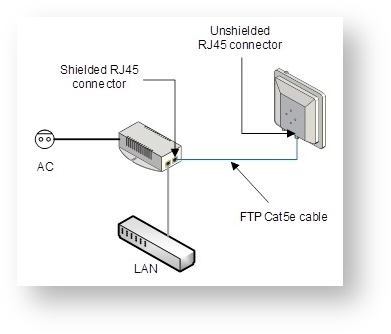
- Determine the FTP cable length that is used to connect IDU and ODU. The total cable length between LAN (behind IDU) and ODU should not be longer than 100 meters. Service cable connecting IDU and ODU should be FTP Cat5e cable with the outside diameter value not more than 7mm.
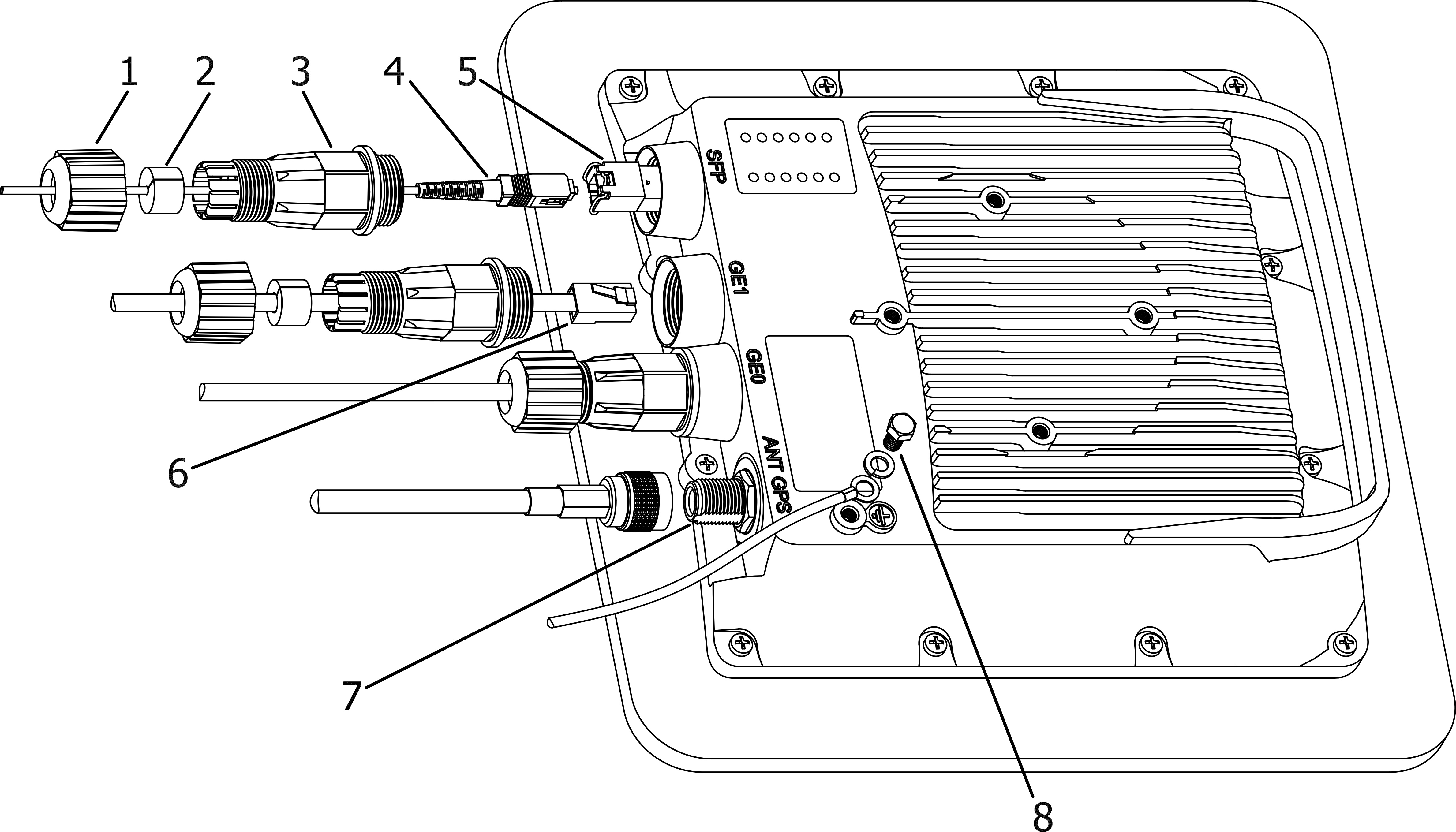
If using SFP module, connect it to ODU, plug in the optical cable (the maximum length and type depend on the SFP module type) and seal the connector
Center Scroll Title title 1 - Cable gland nut, 2 - Split sealing grommet, 3 - Cable gland threaded coupling, 4 - Optical cable (from 2mm to 3 mm), 5 - SFP-module (not included in the delivery package), 6 - Standard RJ-45 connector, 7 - GPS antenna port (antenna and cable are not included in the delivery package), 8 - Grounding bolt.
Figure - InfiLINK XG - Xm ODU Installation Procedure- Install (crimp) regular RJ-45 connector for ODU on the FTP cable and seal it. Do not use the shielded RJ-45 connector on this end of the cable, as it should be attached only on the IDU end.
- Lay the FTP cable (and the optical cable, if used) “from top to bottom” - from ODU to IDU.
- Install (crimp and solder) shielded RJ-45 connector for IDU on the FTP cable.
Install ODU on the mounting bracket, connectors facing down, and tighten it.
Note title NOTE It is very important to mount the ODU connectors facing down.
- Connect the ODU-IDU cable to the ODU.
- Seal the ODU Ethernet connectors.
- Once the ODU and pole are installed they must be properly grounded: connected to the building lightning protection circuit. The ODU position must be lower than the highest pole point at least by 2 ODU heights.
- Connect the FTP cable to IDU, after previously having touched IDU connector case with FTP cable connector case.
- Provide grounding for IDU.
- Connect Ethernet cable to IDU.
- Connect the IDU to power.
- Connect to the device using Telnet protocol.
| Center | |||||||||||||||||||||||||||
|---|---|---|---|---|---|---|---|---|---|---|---|---|---|---|---|---|---|---|---|---|---|---|---|---|---|---|---|
|