| Include Page | ||||
|---|---|---|---|---|
|
| Table of Contents |
|---|
Introduction
This document is intended to demonstrate InfiNet Infinet Wireless devices potential performance. The data used in the document is obtained through laboratory testing. The parameters of communication channels in real conditions may differ from the presented, however, under conditions of minimal external influence, the obtained values are achievable in practice.
...
The parameter configuration influence will be described within this document. The article contains several InfiNet Infinet Wireless hardware platforms, characteristic set of parameters that affect the performance will be specified for each.
Факторы, определяющие характеристики канала
Модуляционно-кодовая схема
Выбранная модуляционно-кодовая схема для передачи данных определяет пропускную способность канала связи. Для подтверждения высказывания рассмотрим пример (см. рисунок 1).
Рассмотрим пример, в котором будем передавать шесть бит информации - "100111". В первом случае, для передачи информационной последовательности будем использовать модуляционно-кодовую схему QPSK 3/4, во втором - QAM16 1/2. В качестве помехоустойчивого кода используется код проверки на чётность.
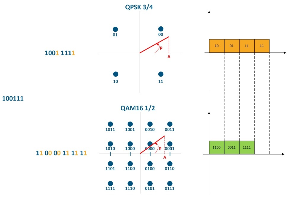
На рисунке 1 представлены сигнальные созвездия для рассматриваемых видов модуляций - QPSK 3/4 и QAM16 1/2. Каждая из точек соответствует определённому значению амплитуды (A) и фазы (ф) сигнала, а каждому из этих сигналов поставлен в соответствие набор бит. Формируя сигнал с заданными значениями амплитуды и фазы, передаётся соответствующий набор данных, а совокупность всех сигналов (точек созвездия) называется разрешёнными состояниями. Чем больше число разрешённых состояний, тем больше бит может быть передано сигнальной посылкой с заданными характеристиками амплитуды и фазы.
...
Factors which determines channel characteristic
The modulation code scheme
The selected modulation code scheme for data transmission determines the communication channel throughput. Let's look at the example (see Figure 1) to confirm the statment.
Let's look at the example, we will transmitt 6 bit of information - "100111". In the first case, for the information sequence transmission, we will use the QPSK 3/4 modulation code scheme, in the second case - QAM16 1/2. The parity check code is used as the error-control code.
At the Figure 1 signal constellations for modulation code schemes QPSK 3/4 and QAM16 1/2 are shown. Each point corresponds to a certain amplitude value (A) and phase (p) of the signal, and a set of bits is assigned to each of these signals. By forming a signal with given amplitude and phase values, the corresponding data set is transmitted, and the set of all signals (constellation points) is called allowed states. The greater the number of allowed states, the more bits can be transmitted by a signal element with given amplitude and phase characteristics.
When using QPSK 3/4 modulation, each three bits information sequence will be complemented by one bit of parity check, those instead of the original six bits sequence, eight bits will be transmitted - "10011111". Число разрешённых состояний сигнала для модуляции QPSK равно четырём The allowed signal states number for QPSK modulation is four (22), поэтому одним сигналом в единицу времени (сигнальная посылка) можно передать два бита помехоустойчивой последовательности. Таким образом, для передачи восьми бит полученной последовательности потребуется четыре сигнальных посылки , therefore, one signal per unit of time (signal element) can transmit two bits of an error-control sequence. Thus, to transmit eight bits of the received sequence, four signal elements (8/2 = 4 сигнальных посылкиsignal elements) are required.Для модуляции
For QAM16 1/2 каждый информационный бит дополняется одним битом проверки на чётность - исходная последовательность из шести бит преобразуется в последовательность из 12 бит modulation, each information bit is complemented by one parity check bit — the original six-bit sequence is converted to a 12-bit sequence "110000111111". Число разрешённых состояний сигнала для модуляции QAM16 The allowed signal states number for QAM16 1/2 равно шестнадцати modulation is sixteen (24), поэтому одним сигналом в единицу времени (сигнальная посылка) можно передавать четыре бита помехоустойчивой последовательности. Таким образом, для передачи двенадцати бит полученной последовательности потребуется три сигнальных посылки , therefore, one signal per unit of time (signal element) can transmit four bits of an error-control sequence. Thus, to transmit twelve bits of the received sequence, three signal elements (12/4=3 сигнальных посылки)3 signal elements) are required.
Таким образом, шесть бит исходной информационной последовательности с помощью Thus, six bits of the original information sequence using QPSK 3/4 были переданы за четыре временных интервала, а с помощью were transmitted in four time slots, and using QAM16 1/2 - за три, свидетельствует о превосходстве модуляционно-кодовой схемы in three, this demonstrates the QAM16 1/2 в канальной и информационной скорости. Использование высоких модуляционно-кодовых схем позволяет повысить производительность канала связи, увеличив пропускную способность, однако, как это показано в онлайн-курсе, использование высоких модуляционно-кодовых схем возможно только для радиоканалов с большим энергетическим запасом.
В устройствах семейства R5000 тип модуляционно-кодовой схемы выражен через битрейт, в устройствах семейства XG отображается MCS как таковая. В целях унификации и исключения путаницы, далее в документе будет использоваться индекс MCS (модуляционно-кодовая схема). Соответствие между индексом и модуляцией приведено в таблице ниже.
Таблица соответствия модуляционно-кодовой схемы и битрейта R5000
...
modulation code scheme advantage in channel and information rate. The high modulation code schemes using can improve the communication channel performance by increasing the throughput, however, as it is shown in the online course, the high modulation code schemes using is possible only for radio channels with a large link margin.
In the InfiLINK 2x2, InfiMAN 2x2, InfiLINK Evolution and InfiMAN Evolutionfamilies devices, the modulation code scheme type is shown as a bitrate, in the InfiLINK XG and InfiLINK XG 1000 families devices, MCS itself is displayed. In order to eliminate confusions, in the document below the MCS (modulation code scheme) index will be used. The correspondence between modulation and index is shown in the table below.
Table of the correspondence between modulation code scheme and bitrate in InfiLINK 2x2, InfiMAN 2x2 devices
| Center | ||||||||||||||||||||||||||||||||||||||||||||||||||||||||||||||
|---|---|---|---|---|---|---|---|---|---|---|---|---|---|---|---|---|---|---|---|---|---|---|---|---|---|---|---|---|---|---|---|---|---|---|---|---|---|---|---|---|---|---|---|---|---|---|---|---|---|---|---|---|---|---|---|---|---|---|---|---|---|---|
| ||||||||||||||||||||||||||||||||||||||||||||||||||||||||||||||
Таблица соответствия индекса и модуляционно-кодовой схемы XG
| Center | ||
|---|---|---|
|
Table of the correspondence between modulation code scheme and bitrate in InfiLINK Evolution, InfiMAN Evolution
| Center | ||||||||||||||||||||||||||||||||||||||||||||||||||||||||||||
|---|---|---|---|---|---|---|---|---|---|---|---|---|---|---|---|---|---|---|---|---|---|---|---|---|---|---|---|---|---|---|---|---|---|---|---|---|---|---|---|---|---|---|---|---|---|---|---|---|---|---|---|---|---|---|---|---|---|---|---|---|
| ||||||||||||||||||||||||||||||||||||||||||||||||||||||||||||
Table of the correspondence between MCS index and modulation type in InfiLINK XG/InfiLINK XG 1000 family devices
| Center | ||||||||||||||||||||||||
|---|---|---|---|---|---|---|---|---|---|---|---|---|---|---|---|---|---|---|---|---|---|---|---|---|
|
Table of the correspondence between MCS index and modulation type in Quanta 5, Quanta 6 families devices
| Center | ||||||||||||||||||||||||||||||
|---|---|---|---|---|---|---|---|---|---|---|---|---|---|---|---|---|---|---|---|---|---|---|---|---|---|---|---|---|---|---|
|
Table of the correspondence between MCS index and modulation type in Quanta 70 family devices
| Center | ||||||||||||||||||
|---|---|---|---|---|---|---|---|---|---|---|---|---|---|---|---|---|---|---|
|

 Рисунок
1 - Влияние модуляционно-кодовой схемы на пропускную способность канала связиFigure 1 - The impact of the modulation code scheme on the communication channel throughput
| Anchor | ||||
|---|---|---|---|---|
|
...
На практике в сети одновременно передаётся множество кадров различной длины, поэтому полезно оценить параметры качества канала связи, сгенерировав трафик, состоящий из кадров заданного размера. Тестирование производится для кадров размером от 64 до 1518 байт, что регламентируется протоколом Ethernet.
Для пояснения влияния размера кадра на полезную пропускную способность канала связи рассмотрим структуру кадра Ethernet (см. рисунок 2а). Кадр Ethernet состоит из двух служебных полей постоянной длины: заголовка (14 байт) и поля контрольной суммы (4 байт), и поля данных (46-1500 байт), т.е. общий размер кадра находится в диапазоне 64-1518 байт.
Рассмотрим задачу, в которой необходимо передать 1500 байт информации, поместив данные в Ethernet-кадры. Для этого будет использовать кадры различной длины: 1518 байт (рисунок 2б), 518 байт(рисунок 2в), 268 байт (рисунок 2г). Сводная информация о размерах служебных заголовков и его доле в потоке данных приведена в таблице ниже. Видно, что с уменьшением размера кадра затраты на передачу служебных заголовков существенно увеличивается, а доля полезных данных уменьшается.
...
Рисунок 2 - Структура Ethernet-кадра: а - общая структура, б - кадр с полем данных длиной 1500 байт, в - кадры с полями данных длиной 500 байт, г - кадры с полями данных длиной 250 байт
С уменьшением размера кадров увеличивается доля накладных расходов для служебных заголовков, регламентируемых требованиями протокола передачи данных, как это показано в таблице выше. Логичным решением по повышению эффективности передачи данных является использование кадров максимальной длины. Однако кадры меньшего размера быстрее обрабатываются сетевым оборудованием, что снижает время распространения кадра от источника к получателю. Для некоторых видов трафика время распространения является критичным. Для трафика реального времени, например голосового трафика, снижение размера кадра является вынужденным, потому что ключевым показателем качества канала связи в этом случае является не пропускная способность, а величина задержки. Следовательно данные должны отправляться как можно быстрее, более мелкими порциями.
В общем случае величина задержки зависит от:
- времени распространения радиосигнала (зависит от среды распространения);
- времени обработки кадра (зависит от пакетной производительности устройства);
- времени нахождения в очереди (зависит от уровня загрузки канала связи, величины буферов памяти устройства и конфигурации QoS).
Ширина частотного канала
При установке радиоканала между двумя устройствами, для них выбирается несущая частота F1, спектр которой представлен на рисунке 3а. Такой сигнал не несёт информации, поскольку его основные параметры (амплитуда, частота, фаза) известны и неизменны, т.е. можно предсказать состояние сигнала в любой из будущих периодов времени. Для того, чтобы радиосигнал стал носителем информации, его параметры изменяют в соответствии с потоком данных. Этот процесс называется модуляцией. В процессе модуляции изменяются основные параметры сигнала и преобразуется его спектр - теперь сигнал занимает определённую полосу частот ΔF (см. рисунок 3б).
Следует заметить, что ширина частотного канала влияет на доступный набор модуляционно-кодовых схем и, как следствие, на производительность канала. Таким образом, увеличение пропускной способности радиоканала может быть доступно с помощью расширения занимаемой полосы частот.

...
Frame size
In practice, at the same time, multiple frames of different length are transmitted in the network, so it is useful to evaluate the link quality parameters by generating traffic consisting of frames with a given size. Testing is performed for frames with sizes from 64 to 1518 bytes, which is regulated by the Ethernet protocol.
To explain the frame size effect on the useful throughput of the communication channel, let's look at the Ethernet frame structure (see Figure 2a). An Ethernet frame consists of two service fields with constant length: a header (14 bytes) and a checksum field (4 bytes), and a data field (46-1500 bytes), i.e. total frame size is in the range of 64-1518 bytes.
Let's look at the task in which we need to transfer 1500 bytes of information by placing the data in Ethernet frames. In order to do this we will use frames of different lengths: 1518 bytes (Figure 2b), 518 bytes (Figure 2c), 268 bytes (Figure 2d). Summary information about the service headers size and its share in the data stream is given in the table below. We can see that with decreasing frame size, the cost of transmitting service headers significantly increases, while the share of payload data decreases.
| Center | ||||||||||||||||
|---|---|---|---|---|---|---|---|---|---|---|---|---|---|---|---|---|
|
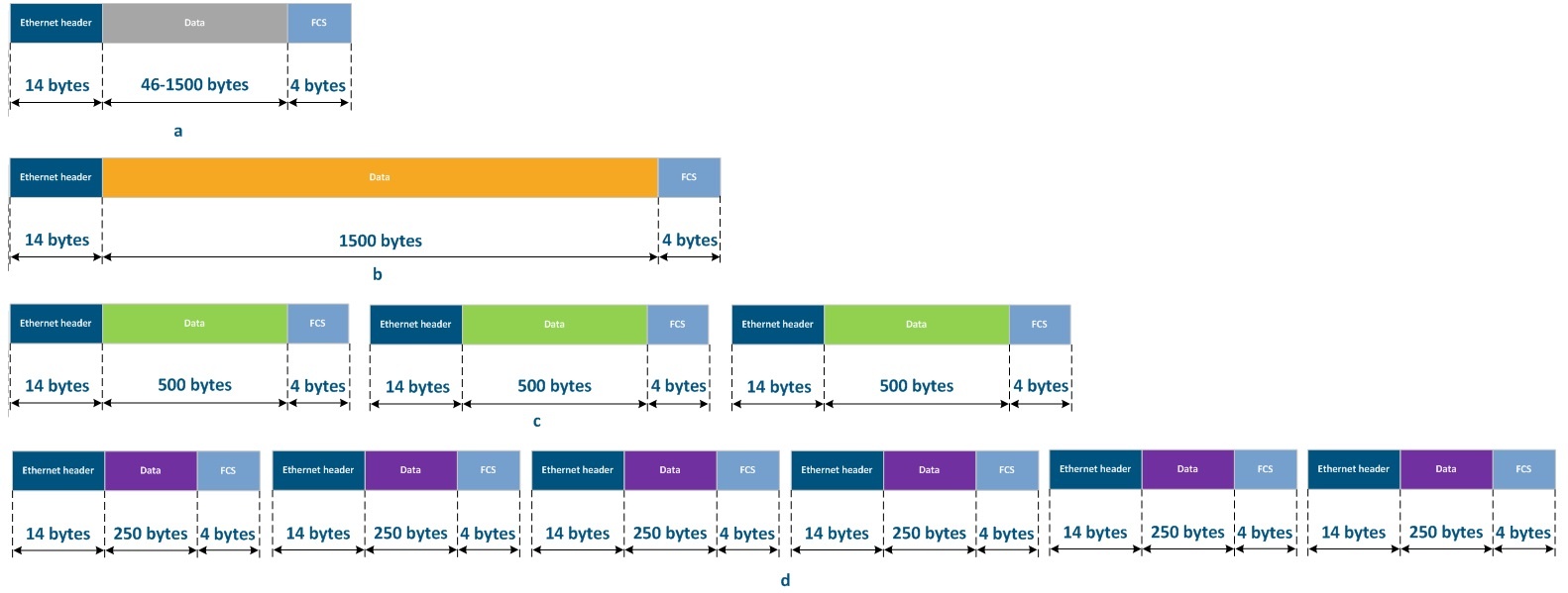
Figure 2 - Ethernet frame structure: a - general structure, b - frame with 1500 bytes data field, c - frames with 500 byte data fields, d - frames with 250 byte data fields
With decreasing frame size, the share of overhead costs for service headers (regulated by the requirements of the data transfer protocol, as shown in the table above) increases. The solution for improving the efficiency of data transfer by using maximum length frames seems obvious. However, small frames are processed faster by network equipment, it reduces the time to propagate a frame from source to destination. Distribution time is critical parameter for some types of traffic. For real-time traffic, such as voice traffic, a reduction in frame size is forced, because the key indicator of the link quality in this case is not the throughput, but the delay value. Therefore, the data should be sent as quickly as possible, in smaller portions.
In general, the delay value depends on:
- the radio signal propagation time (depends on the propagation medium);
- frame processing time (depends on the device's packet performance);
- time spent in the queue (depends on the link loading level, the size of the device memory buffers and QoS configuration).
Frequency channel width
When a radio channel is established between two devices, F1 carrier frequency is selected for them, the spectrum of which is shown in Figure 3a. Such a signal does not carry information, since its main parameters (amplitude, frequency, phase) are known and unchanged, i.e. it's possible to predict the state of the signal in any future time period. In order for the radio signal to become an information carrier, its parameters are changed in accordance with the data flow. This process is called modulation. In the modulation process, the basic parameters of the signal are changed and its spectrum is transformed - now the signal occupies a certain frequency band ΔF (see Figure 3b).
Note that the frequency channel width affects the available set of modulation code schemes and the link performance. Thus, the radio link capacity increasement can be accessed by expanding the occupied bandwidth.
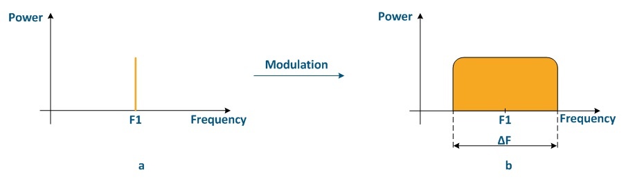
Figure 3 - Signal spectrum: a - carrier frequency, b - modulated signal
| Anchor | ||||
|---|---|---|---|---|
|
...
Для пояснения влияния размера радиокадра на параметры качества канала связи рассмотрим соединение двух устройств (XG или R5000 с прошивкой TDMA). Механизм передачи информации в радиосреде представлен ниже (см. рисунок 4). Подробное описание механизмов передачи данных при TDMA и Polling представлено в TDMA и Polling: особенности применения в беспроводных сетях. Под радиокадром понимается период времени, в рамках которого выполняется обслуживание сектором одного абонентского устройства. В течение одного радиокадра происходит обмен данными между двумя устройствами в нисходящем и восходящем потоках.
Аналогично кадрам Ethernet часть радиокадра отдана под служебные нужды. В частности, обязательными являются поле синхронизации и защитный интервал (guard interval), которые не зависят от размера радиокадра. Оставшееся время передаются полезные данные. Таким образом, аналогично кадрам Ethernet, большее значение длины радиокадра приведёт к более эффективной утилизации канала связи, однако вместе с этим увеличится величина задержки (следующий пакет данных может быть передан только в следующий интервал передачи, а чем больше длина радиокадра - тем больше время ожидания).

Рисунок 4 - Механизм передачи данных при TDMA и TDD
Дальность связи
Параметр "Максимальное расстояние" влияет на величину защитного интервала guard (см. рисунок 4), а значит на эффективность использования пропускной способности канала связи. Кроме того, фактическая дальность расположения абонентской станции влияет на время распространения радиосигнала в среде.
Число абонентских станций
Дополним рисунок из раздела "Длительность радиокадра", добавив ещё два абонентских устройства (см. рисунок 5).
Время ожидания передачи пропорционально числу абонентских станций, т.к.для обмена данными с каждой станцией выделяется временной интервал, равный длине радиокадра. Таким образом, величина задержки зависит от числа активных абонентов.

Рисунок 5 - Механизм передачи данных при TDMA для трёх абонентских станций
Набор фирменных параметров
Опция Greenfield
Опция Greenfield устанавливается как на устройствах Master, так и на Slave и отвечает за включение оптимизации служебной информации, передаваемой через радиоканал. Оптимизация позволяет существенно снизить объём служебной информации и улучшить производительность на 10-15% за счёт увеличения объёма полезных данных в радиокадре.
Опция VBR
Оция VBR (variable bitrate - переменный битрейт) устанавливается на ведомом устройстве и позволяет повысить эффективность при передаче служебных данных. При отключенной опции VBR служебные поля сообщений Sync передаются с использованием минимальной модуляционно-кодовой схемы. При активации VBR, поля Sync будут передаваться на модуляционно-кодовой схеме выше минимальной, если есть такая возможность. Это позволит передать синхропоследовательность быстрее, что снизит долю служебных сообщений в общем времени передачи и повысит производительность канала связи.
...
Radio frame period
To explain the radio frame period effect on the link quality parameters, let's look at the connection of two devices (InfiLINK XG/InfiLINK XG 1000 or R5000 with TDMA firmware). The transmitting information mechanism in the radio medium is presented below (see Figure 4). For detailed description of the data transfer mechanisms for TDMA and Polling see TDMA and Polling: Application features. A radio frame is a time period within which a subscriber terminal is serviced by a sector. During one radio frame, data is exchanged between two devices in the downstream and upstream.
Similar to Ethernet frames, a part of the radio frame is allocated for service traffic. In particular, the synchronization field and guard interval are obligatory and do not depend on radio frame period The remaining time useful data is transmitted. Thus, same as the Ethernet frames, a longer radio frame length will lead to more efficient utilization of the communication channel, but the delay value will increase (the next data packet can be transmitted only in the next transmission interval, and the longer the radio frame is, the longer the waiting time).
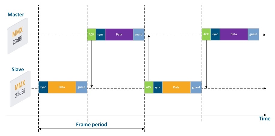
Figure 4 - The transmitting data mechanism for TDMA and TDD
Distance range
The "Maximum distance" parameter affects the guard interval value (see Figure 4), and also the efficiency of using the link throughput. In addition, the actual farness of the subscriber terminal affects the radio signal propagation time in the media.
Number of subscriber devices
Let's add to the picture from the "Radio frame period", section two more subscriber devices (see Figure 5).
The transmission waiting time is proportional to the number of subscriber devices, since a time interval equal to the frame period is allocated for data exchange with each station. Thus, the delay value depends on the number of active subscribers.
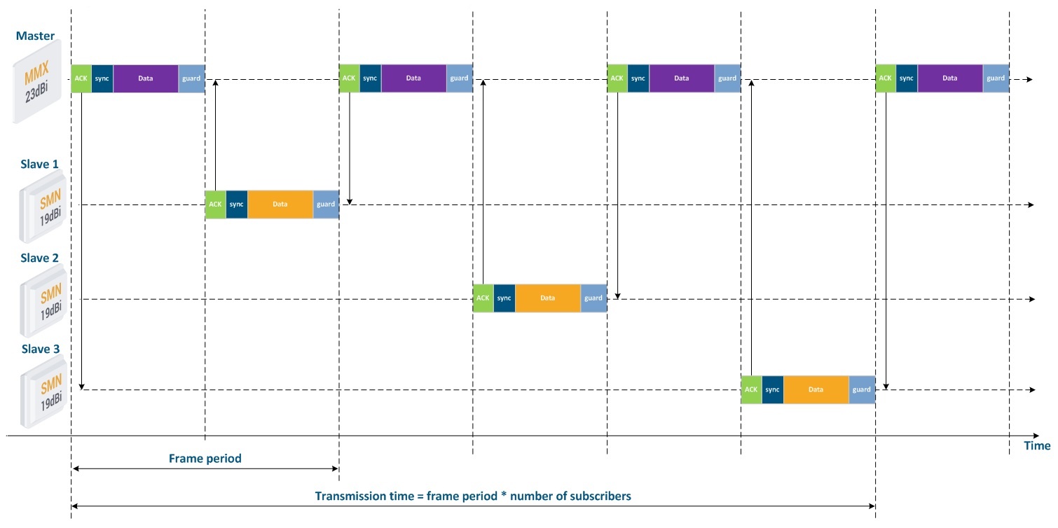
Figure 5 - The transmitting data mechanism for TDMA with three subscriber terminals
Propriate parameters set
Greenfield
The Greenfield option is activated on both Master and Slave devices and is responsible for optimization of service information transmitted via the radio link. Optimization significantly reduces the amount of service information and improve performance by 10-15% due to an increase of useful data share in the radio frame.
VBR
The VBR option (variable bitrate) can be configured on the slave device and allows to increase efficiency of the service data transmission. With the VBR option disabled, the Sync message service fields are transmitted using a minimum modulation code scheme. When VBR is enabled, Sync fields will be transmitted on the modulation code scheme higher then the minimal, if possible. This allows to transmit the sync sequence faster, reduces the share of service messages in the total transmission time and increases the link performance
The VBR option is available only on the InfiLINK 2x2, InfiMAN 2x2 families devices with software that supports TDMA technology and on the InfiLINK Evolution, InfiMAN Evolution families devices.