| Include Page | ||||
|---|---|---|---|---|
|
| Table of Contents |
|---|
Introduction
This document is intended to demonstrate InfiNet Infinet Wireless devices potential performance. The data used in the document is obtained through laboratory testing. The parameters of communication channels in real conditions may differ from the presented, however, under conditions of minimal external influence, the obtained values are achievable in practice.
...
The parameter configuration influence will be described within this document. The article contains several InfiNet Infinet Wireless hardware platforms, characteristic set of parameters that affect the performance will be specified for each.
Factors which determines channel characteristic
The modulation code scheme
The selected modulation code scheme for data transmission determines the communication channel throughput. Let's look at the example (see Figure 1) to confirm the statment.
...
Thus, six bits of the original information sequence using QPSK 3/4 were transmitted in four time slots, and using QAM16 1/2 - in three, this demonstrates the QAM16 1/2 modulation code scheme advantage in channel and information rate. The high modulation code schemes using can improve the communication channel performance by increasing the throughput, however, as it is shown in the online course, the high modulation code schemes using is possible only for radio channels with a large link margin.
In the R5000 family InfiLINK 2x2, InfiMAN 2x2, InfiLINK Evolution and InfiMAN Evolutionfamilies devices, the modulation code scheme type is shown as a bitrate, in the InfiLINK XG and InfiLINK XG 1000 families devices, MCS itself is displayed. In In order to eliminate confusions, in the document below the MCS (modulation code scheme) index will be used. The The correspondence between modulation and index is shown in the table below.
Table of the correspondence between modulation code scheme and bitrate in
...
InfiLINK 2x2, InfiMAN 2x2 devices
| Center | ||||||||||||||||||||||||||||||||||||||||||||||||||||||||||||
|---|---|---|---|---|---|---|---|---|---|---|---|---|---|---|---|---|---|---|---|---|---|---|---|---|---|---|---|---|---|---|---|---|---|---|---|---|---|---|---|---|---|---|---|---|---|---|---|---|---|---|---|---|---|---|---|---|---|---|---|---|
| ||||||||||||||||||||||||||||||||||||||||||||||||||||||||||||
Table of the correspondence between modulation code scheme and bitrate in InfiLINK Evolution, InfiMAN Evolution
| Center | ||||||||||||||||||||||||||||||||||||||||||||||||||||||||||||
|---|---|---|---|---|---|---|---|---|---|---|---|---|---|---|---|---|---|---|---|---|---|---|---|---|---|---|---|---|---|---|---|---|---|---|---|---|---|---|---|---|---|---|---|---|---|---|---|---|---|---|---|---|---|---|---|---|---|---|---|---|
| ||||||||||||||||||||||||||||||||||||||||||||||||||||||||||||
Table of the correspondence between MCS index and modulation type in InfiLINK XG/InfiLINK XG 1000 family devices
| Center | ||||||||||||||||||||||||
|---|---|---|---|---|---|---|---|---|---|---|---|---|---|---|---|---|---|---|---|---|---|---|---|---|
|
Table of the correspondence between MCS index and modulation type in Quanta 5, Quanta 6 families devices
| Center | ||||||||||||||||||||||||||||||
|---|---|---|---|---|---|---|---|---|---|---|---|---|---|---|---|---|---|---|---|---|---|---|---|---|---|---|---|---|---|---|
|
Table of the correspondence between MCS index and modulation type in Quanta 70 family devices
| Center | ||||||||||||||||||
|---|---|---|---|---|---|---|---|---|---|---|---|---|---|---|---|---|---|---|
|
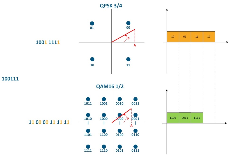
Figure 1 - The impact of the modulation code scheme on the communication channel throughput
| Anchor | ||||
|---|---|---|---|---|
|
In practice, at the same time, multiple frames of different length are transmitted in the network, so it is useful to evaluate the link quality parameters by generating traffic consisting of frames with a given size. Testing is performed for frames with sizes from 64 to 1518 bytes, which is regulated by the Ethernet protocol.
...
- the radio signal propagation time (depends on the propagation medium);
- frame processing time (depends on the device's packet performance);
- time spent in the queue (depends on the link loading level, the size of the device memory buffers and QoS configuration).
Frequency channel width
When a radio channel is established between two devices, F1 carrier frequency is selected for them, the spectrum of which is shown in Figure 3a. Such a signal does not carry information, since its main parameters (amplitude, frequency, phase) are known and unchanged, i.e. it's possible to predict the state of the signal in any future time period. In order for the radio signal to become an information carrier, its parameters are changed in accordance with the data flow. This process is called modulation. In the modulation process, the basic parameters of the signal are changed and its spectrum is transformed - now the signal occupies a certain frequency band ΔF (see Figure 3b).
...
Figure 3 - Signal spectrum: a - carrier frequency, b - modulated signal
| Anchor | ||||
|---|---|---|---|---|
|
To explain the radio frame period effect on the link quality parameters, let's look at the connection of two devices (InfiLINK XG/InfiLINK XG 1000 or R5000 with TDMA firmware). The transmitting information mechanism in the radio medium is presented below (see Figure 4). For detailed description of the data transfer mechanisms for TDMA and Polling see TDMA and Polling: Application features. A radio frame is a time period within which a subscriber terminal is serviced by a sector. During one radio frame, data is exchanged between two devices in the downstream and upstream.
...
Figure 4 - The transmitting data mechanism for TDMA and TDD
Distance range
The "Maximum distance" parameter affects the guard interval value (see Figure 4), and also the efficiency of using the link throughput. In addition, the actual farness of the subscriber terminal affects the radio signal propagation time in the media.
Number of subscriber devices
Let's add to the picture from the "Radio frame period", section two more subscriber devices (see Figure 5).
...
Figure 5 - The transmitting data mechanism for TDMA with three subscriber terminals
Propriate parameters set
Greenfield
The Greenfield option is activated on both Master and Slave devices and is responsible for optimization of service information transmitted via the radio link. Optimization significantly reduces the amount of service information and improve performance by 10-15% due to an increase of useful data share in the radio frame.
VBR
The VBR option (variable bitrate) can be configured on the slave device and allows to increase efficiency of the service data transmission. With the VBR option disabled, the Sync message service fields are transmitted using a minimum modulation code scheme. When VBR is enabled, Sync fields will be transmitted on the modulation code scheme higher then the minimal, if possible. This allows to transmit the sync sequence faster, reduces the share of service messages in the total transmission time and increases the link performance
The VBR option is available only on the R5000 family devices InfiLINK 2x2, InfiMAN 2x2 families devices with software that supports TDMA technology and on the InfiLINK Evolution, InfiMAN Evolution families devices.