| Include Page | ||||
|---|---|---|---|---|
|
| Hide_comments |
|---|
| Note | ||
|---|---|---|
| ||
A minimum set of requirements must be met during devices pre-configuration in the lab:
|
Step 1:
...
Connection scheme
The equipment list required for the lab configuration:
...
- Connect Gigabit Ethernet port at the ODU to the power supply port labeled as "OUT".
- Connect Ethernet port at the laptop to the power supply port labeled as "IN".
- Connect the power cord to power supply and plug it to AC mains.
...
| Gliffy Diagram |
|---|
...
|
Step 2:
...
Access to the device
Let's access each unit to the default IP address 10.10.10.1 with mask 255.255.255.0 via a web browser. Before, make sure the Ethernet port of the Laptop has an IP address assigned from the same subnetwork as the one for the unit (e.g., set 10.10.10.10 with mask 255.255.255.0).
| Note | ||
|---|---|---|
| ||
We assume that each unit used in this setup has not been configured before and runs with the factory settings. |
...
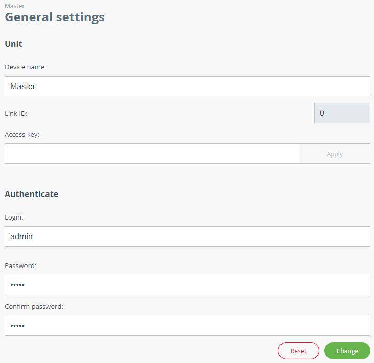
- Device Name (e.g., Master/Slave).
Go to the "Settings" → "Security" section and configure:
- Login (e.g., admin).
- Password (e.g., admin).
| Centernote | |
|---|---|
| |
| |
At the next login, type "admin" for the Login and Password (if these are the credentials set before) to access the unit in the privileged mode. |
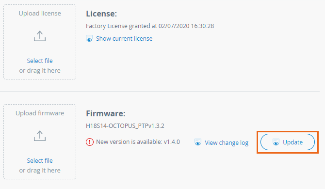
Step 3: Firmware upgrade
Let's upgrade each unit to the latest stable firmware version. Go to the "Maintenance" section and click on the "Check latest release" button. In case a new firmware version is available initiate the firmware upgrade process.Before, make sure the laptop which is connected to the unit has an Internet connection, too. the laptop has an access to the Internet, a new software version will be detected automatically, update on both devices.
Otherwise, the manual firmware upgrade process should be performed:
- Download latest release from the ftp server ftphttps://ftp.infinet.ru/pub/Firmware.
- In the "Maintenance" section click the "Select file" button and set the path to the downloaded file, or drug it to the specified area.
- File will be uploaded to the device. Changes will take force after reboot.
...
...
Step 4: Radio parameters configuration
Let's configure the minimum needed radio parameters to establish the link.
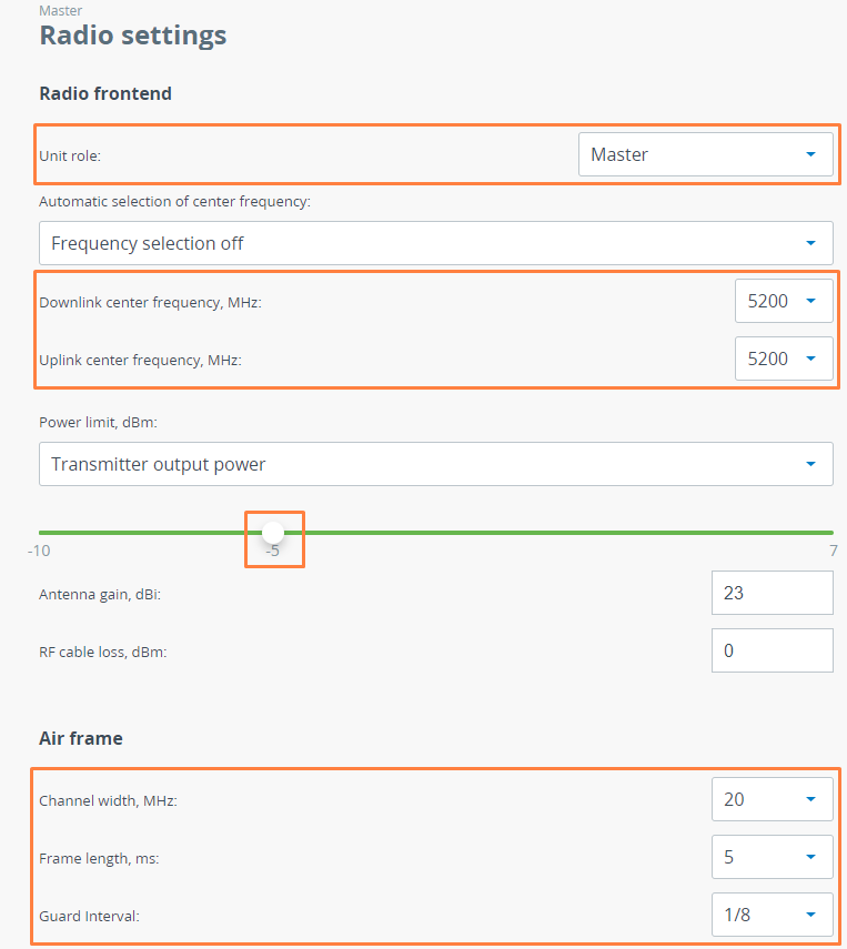
At the unit named Master at step #2 above, go to the "Settings" → "General" section and set the "Link ID" parameter, it must be the same on both sides of the link. Then to "Radio" and set this unit with:
- Unit role: one device should be Master, another one - Slave.
- Downlink center frequency : 5200 MHz ( use values selected at the Link Planning stage).
- Uplink center frequency: 5200 MHzonly for the Slave device.
- Power limit: -5 dBm ( set the minimum value in the range, as currently, we are in the lab, and we don't need high output power anymore).
- Channel width: 20 MHz ( use value selected at the Link Planning stage).
- Frame length: 5 ms.
- Guard interval: 1/8.
The rest of parameters remain with the default values.
| Center |
|---|
|
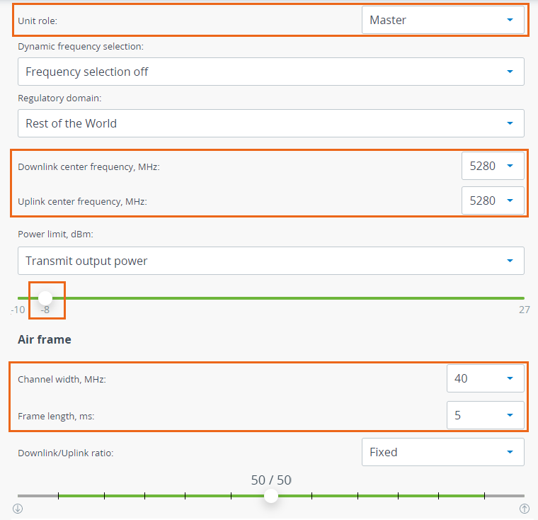
At the unit named Slave at step #2 above, go to the "Settings" → "General" section and set the "Link ID" parameter, it must be the same on both sides of the link. Then to "Radio" and set this unit with:
- Unit role: Slave.
- Downlink center frequency: 5200 MHz (use value selected at the Link Planning stage).
- Power limit: -5 dBm (set the minimum value in the range, as currently, we are in the lab, and we don't need high output power anymore).
- Channel width: 20 MHz (use value selected at the Link Planning stage).
- Frame length: 5 ms.
- Guard interval: 1/8.
- same on both devices.
The rest of parameters remain with the default values.
...
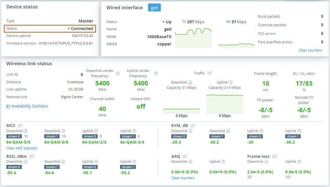
Step 5: Check the wireless link status
Let's apply all settings described above for each unit and go to the "Dashboard" section and check if the device status has changed to "Connected".
...