...
The InfiNet product portfolio includes a wide range of accessories, including mounting kits that allow to install devices in various conditions with the possibility of flexible alignment and the CAB-RV1 alignment tool which allows to perform preliminary device diagnostics.
The MINT protocol
The Ethernet link layer protocol was developed for wired the wired networks and does not take into account the specifics of the wireless environment. Wireless device manufacturers can use standard wireless protocols, such as Wi-Fi, or use their own developmentsself-developed protocols. InfiNet Wireless company is developing has developed a proprietary data transfer protocol called MINT designed , especially designed for data exchange in a wireless environment.
MINT (Mesh Interconnection Network Technolohy) - InfiNet's proprietary technology used in InfiLINK used by the InfiLINK 2x2 and InfiMAN 2x2 family devices, provides data transfer between devices via wireless and wired links.
MINT area
One of the MINT protocol's main concepts is the MINT area. A MINT area consist of many neighboring devices , data and data exchange between them is carried out using MINT frames (see check the "MINT protocol" lesson of the InfiLINK 2x2 and InfiMAN 2x2: Switching online course).
Let's look at the solution described above applying MINT described below, that implements the MINT areas concept (see Figure 4). A radio link is installed between the Master and Slave devices, they form the MINT 5 area. Each of the BS1, BS2, BS3, and BS4 sectors is potentially ready to establish a radio link with the CPE installed on the mobile object , forms and form a separate MINT area with the corresponding identifier.
| Center |
|---|
Figure 4 - Many Multiple MINT areas in the scheme with mobile objectsmobility scenario |
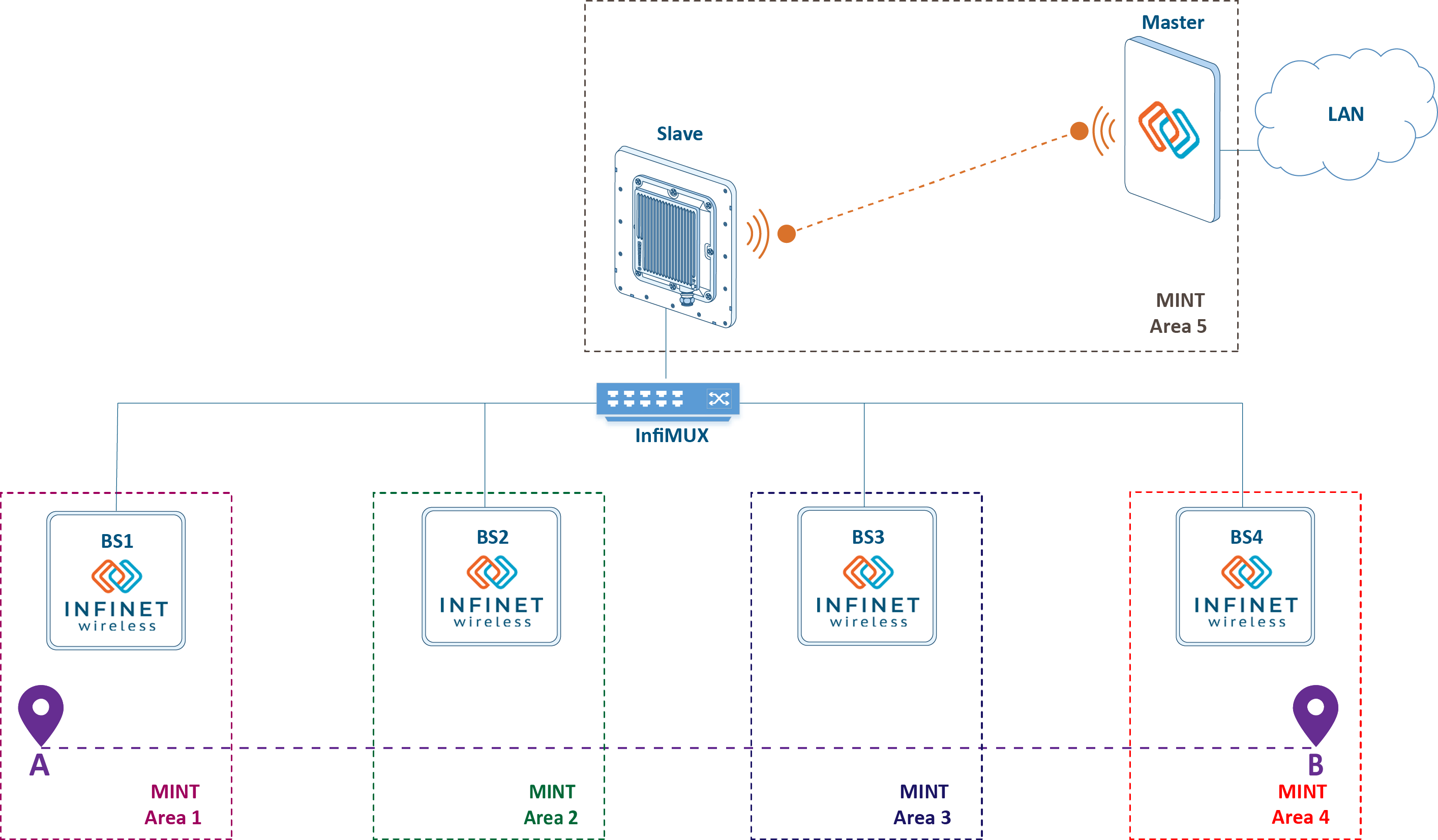
Note that the MINT protocol is intended for data exchange within the MINT area. Data outside the MINT area can be transmitted using other channel protocols, such as Ethernet, i.e. CPE the CPEs and each of the BS sectors is the base stations are the gateway between the MINT and Ethernet networks. In the our scheme, data is exchanged between a mobile object and a control center, i.e. the frame will go through several Ethernet segments and MINT areas in the forward and backward directions. Thus, switch groups group configuration on each device is a prerequisite for data transfer:
| Code Block | ||||||
|---|---|---|---|---|---|---|
| ||||||
switch group 1 add eth0 rf5.0 switch group 1 start switch start |
In addition to Ethernet frames encapsulation during transmission encapsulating the Ethernet frames during the transmission through the MINT area, the MINT protocol performs an exchange of service messages to fill in the frame redirection table. The frame redirection table allows to select the frame transmission route (see video 5) through the MINT area in accordance with the radio parameters and the link load. This mechanism guarantees the selection of the route with the optimal radio parameters and prevents loops.
...
If necessary, you can influence the path selection algorithm by setting the link metrics metric value manually. This can be done by summing the calculated and additional costs or by fixing a certain value (switching in InfiNet devices is detaily described in the online course InfiLINK 2x2 and InfiMAN 2x2: Switching)
...
Data transfer and QoS configuration on each wireless devices device is a time-consuming task that can be simplified by expanding extending the MINT area. Schemes The schemes intended to reduce the wireless devices configuration by combining simplify the configuration of the wireless devices by joining them into a single MINT area, are shown below.
| Anchor | ||||
|---|---|---|---|---|
|
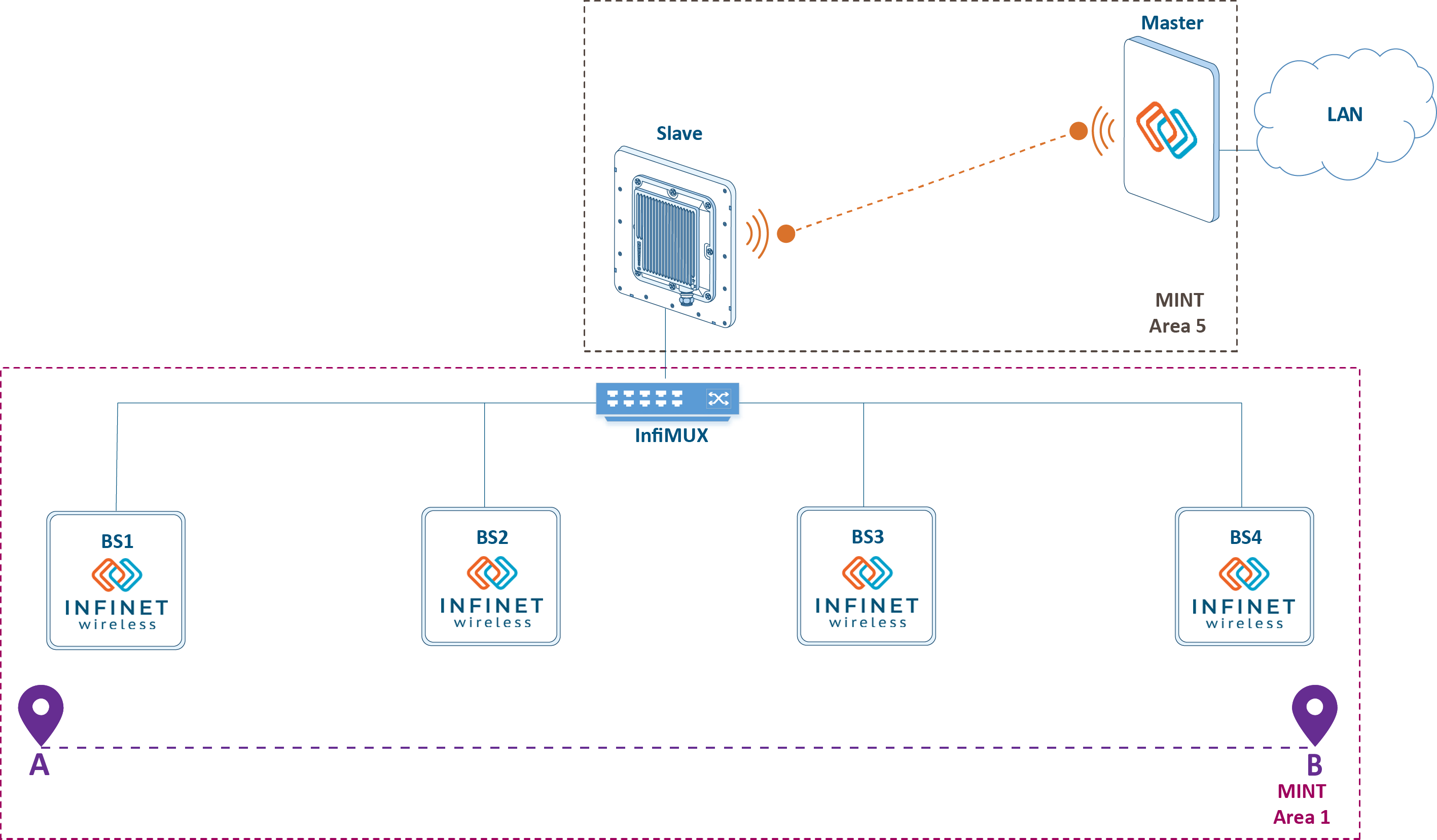
The main disadvantage of the solution above is a necessary switch groups configuration is the necessity to configure switch groups on all wireless devices. Since the switch group is a gateway between MINT and Ethernet, it is possible to combine all the BSs of the radio network into a single MINT area by assigning , transferring the gateway function role to the InfiMUX switch (see Figure 5). In this case, the a switch group is need has to be configured only on the InfiMUX. Joining devices into a single MINT area and the advantages of such a scheme are described in the InfiLINK 2x2 and InfiMAN 2x2: Switching online course.
| Center |
|---|
Figure 5 - Joining the backbone backhaul radio network into a single MINT area |
...