This document contains sub-pages with examples:
Content
Introduction
This document describes the ability of the InfiNet devices to provide sustainable wireless connectivity with mobile objects in various scenarios. A basic deployment is generally presented along with the features related to its implementation for the mining industry, railway and water transport.
Basic requirements
Let's look at the scenario below (Figure 1), which involves the movement of one or more objects throughout the enterprise area along a given path between points A and B. The network control center is located at a certain distance from the area where the moving object can be located.
The project goal is to organize a reliable wireless connectivity between the control center and the mobile objects in order to provide various information services, such as telemetry data gathering, video surveillance, telephony etc.
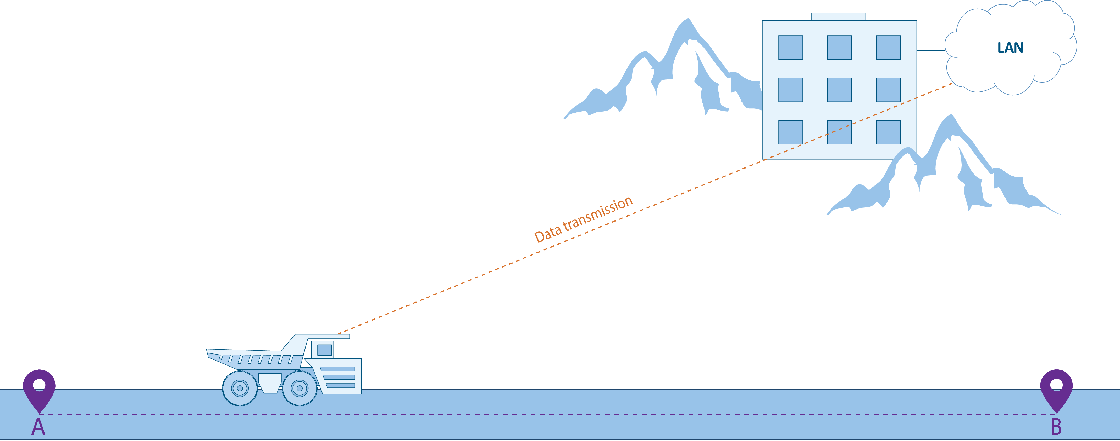
Figure 1 - Basic scenario for connectivity with mobile objects
Two categories of tasks must be solved to achieve this goal:
- Network deployment including the following sections:
- A backhaul radio network. The coverage of the backhaul radio network should correspond to the object's area of motion.
- An aggregation node. The aggregation node is designed to gather the traffic of the backhaul radio network devices and it is a gateway between the radio network and the enterprise network.
- A backbone link between the aggregation node and the control center.
- Fault tolerance and roaming capabilities for:
- Ensuring the link fault tolerance at the access level (backhauling).
- Providing seamless subscriber roaming within the backhaul radio network.
- Ensuring fault tolerance of the main link between the aggregation node and the control center.
- Ensuring the possibility of implementing QoS policies.
Solution
Network deployment
The solution to the tasks described above is shown in Figure 2 and it can be divided into four components:
- The backbone enterprise network
- The aggregation node
- A backhaul radio network
- The object's area of motion
The backhaul radio network consists of several base stations (BS), joined by a wired infrastructure. Each BS can consist of one or several sectors and the combination of their antenna patterns forms the radio network coverage area. The InfiMAN 2x2 family devices can be used as CPEs and BS sectors. Keep in mind that wireless links as well as combined infrastructure can be used to join several BSs.
The base stations are joined by the aggregation node which in our scenario is the InfiMUX device. As shown below, the InfiMUX simplifies the configuration for the InfiNet devices by joining all the BSs into a single MINT area.
A backbone link is established between the aggregation node and the network control center. The choice of specific devices for the radio link is determined by the transmitted traffic capacity (see Performance of the InfiNet Wireless devices). The following throughput values can be achieved:
- InfiLINK 2x2 family devices: up to 280 Mbps.
- InfiLINK XG family devices: up to 500 Mbps.
- InfiLINK XG 1000 family devices: up to 1000 Mbps.
A subscriber station (CPE) is installed on each mobile object and its configuration contains radio profiles for each BS sector in its area of motion. The operational principle is that the CPE can switch the connections while moving between the base stations. Since the BS sectors provide coverage for the entire area in which the CPE can be located, the CPE is always in the coverage area of at least one BS. As soon as the radio parameters of the current connection deteriorate, the CPE interrupts the radio link and connects to another sector. So, while the object moves from point A to point B (Figure 2) the CPE is connecting one by one to the sectors of BS1, BS2, BS3 and BS4.
Keep in mind that the CPE cannot be simultaneously connected to two base stations, because the device has one radio module, so the roaming between the base station sectors is accompanied by a short-term connectivity break. Several CPEs can be simultaneously connected to one BS sector.
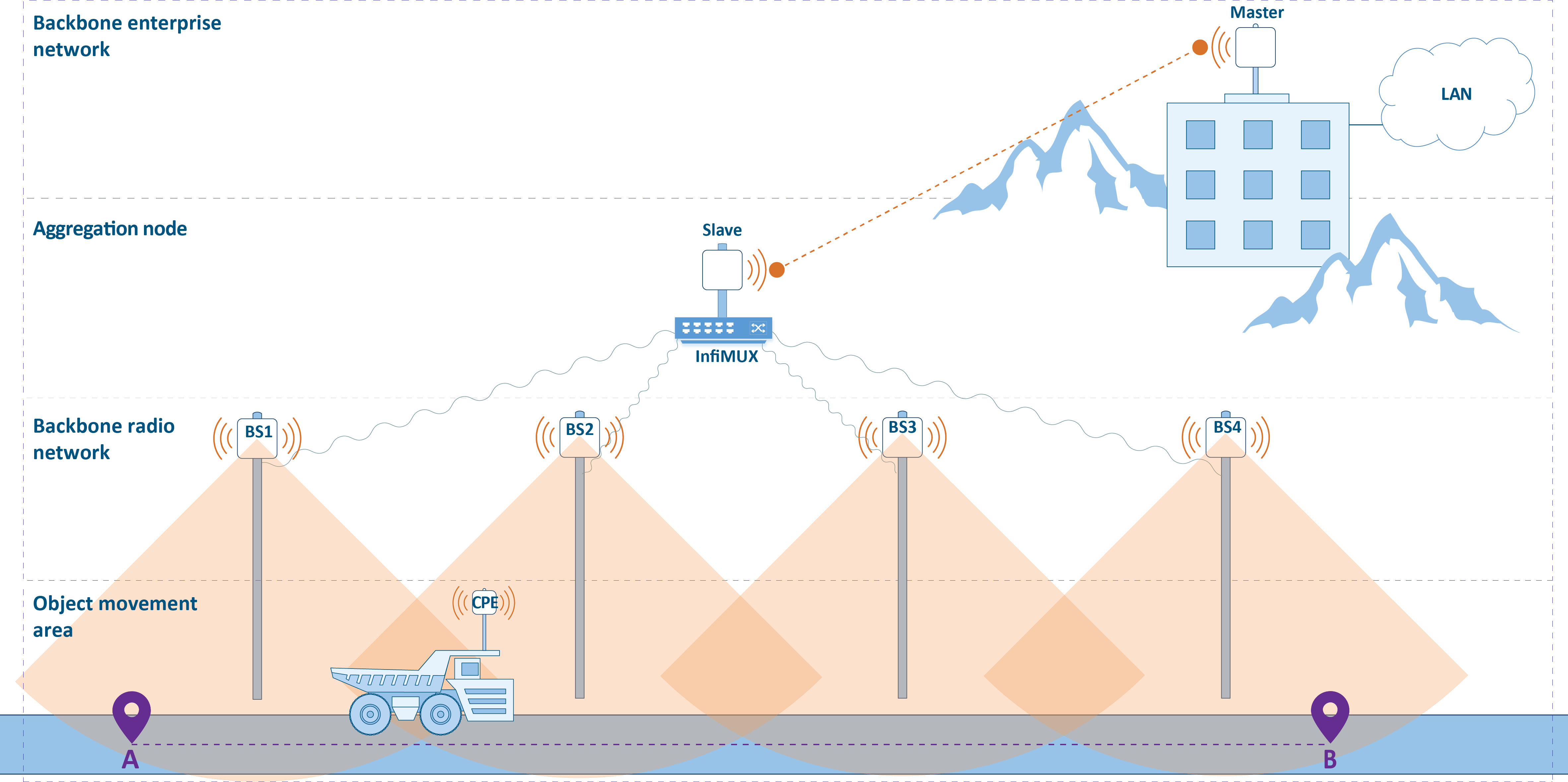
Figure 2 - Distribution of areas
Fault tolerance and roaming
In addition to the infrastructure described earlier there is an extended list of requirements, which make the solution fault-tolerant and more efficient:
- The link fault tolerance at the access level is ensured by overlapping the sectors' radiation patterns at the backhaul radio network design stage. So, if there is more than 50% overlapping with the neighboring sectors, a failure in one of the sectors will not affect the coverage area of the radio network. Radio frequency planning requires a complex approach and it is discussed in more detail in the following sections.
- As noted, roaming in the proposed solution is not seamless, because the roaming between different base stations is accompanied by a connectivity break. A seamless roaming requires the installation of a second CPE device on each moving object. Such a solution is described below.
- InfiNet devices can be used in various scenarios of point-to-point link reservation and aggregation. For example, the backbone link can be reserved using the proprietary failover technology which requires the installation of a second backup wireless link. Failover allows automatic reservation of the backbone link using only one frequency channel. The options for organizing link reservation are presented in the Link aggregation, balancing and redundancy document.
The implementation of a QoS policy does not require the installation of additional devices and it is solved by configuring the wireless units and the InfiMUX device:
- The telemetry gathering service, telephony and remote control are sensitive to delay and jitter, so they require careful configuration of traffic distribution rules by classes. A low jitter for sensitive services can be achieved by using software versions with TDMA technology support on the InfiMAN 2x2 devices. A comparative analysis between the Polling and TDMA multiple access technologies is provided in the TDMA and Polling: Application features document.
- The video surveillance service, in addition to the delay requirements, demands an increased throughput in uplink (from the CPE to the BS). The InfiMAN 2x2 device family supports the time division multiple access method (TDMA), which allows a flexible allocation of the available throughput between the upstream and downstream channels.
- Using a single infrastructure to provide a range of different services requires flexible allocation of the available throughput.
Radio planning
Each implemented solution is unique and requires careful preliminary planning. It is a very important stage, saving resources at the design stage can greatly increase the operational costs. Within this document, the radio frequency planning and placement of the devices will be reviewed.
RF planning
Frequency planning is a complex, creative process that defines:
- The installation coordinates.
- The suspension height, azimuth and antenna elevation.
- The part numbers of the devices.
- The frequency channels and the transmission power.
The result of the frequency planning is a device allocation map with basic radio settings. A convenient tool for radio planning and potential performance assessment depending on the radio parameters is InfiPLANNER.
The frequency channel selection is determined by the following factors:
- Regulatory restrictions: RF regulation is determined at the legislative level. Usually, it is allocated either a frequency range that is allowed for free use with certain restrictions(radiated power, antenna suspension height etc.) or a frequency range for which the permission must be obtained.
- Radio module capabilities: the radio module of the wireless devices supports a limited set of emission frequencies and this should be taken into account at the design stage.
- Physical features of the electromagnetic waves propagation: propagation distance, the effect of precipitation and interaction with obstacles are determined by the electromagnetic wave frequency, which must be kept in mind during preliminary calculations. The radio waves propagation effects are detailed in the Wireless Networking Fundamentals online course.
- The interference level: the operation of third-party wireless devices has a significant impact on the system's performance, so it should be taken into account when designing the link. The interference level is affected by the radiated power and by the frequency channels used by the third-party devices operating in the same area. In addition to interference from third-party devices, the neighboring sectors can have influence on each other. The reducing of the interference between your own devices can be achieved by using different frequency channels. Recommendations for frequency diversity are given in the TDMA and Polling: Application features document. Particular attention should be paid to the frequency channel selection in projects with multisector configurations in order to minimize the influence of the BS sectors on each other.
Some frequency allocation examples are presented below. Figure 3a illustrates a scheme where each BS sector has it's own frequency channel. This approach requires the allocation of 4 frequency channels.
Let's look at the optimized scheme (Figure 3b). Since the sectors' position is chosen in such a way that the radiation patterns of BS1 and BS3, BS2 and BS4 do not intersect in pairs, they will not interfere with each other. This will optimize the frequency resource utilization, reducing the number of frequency channels from 4 to 2.
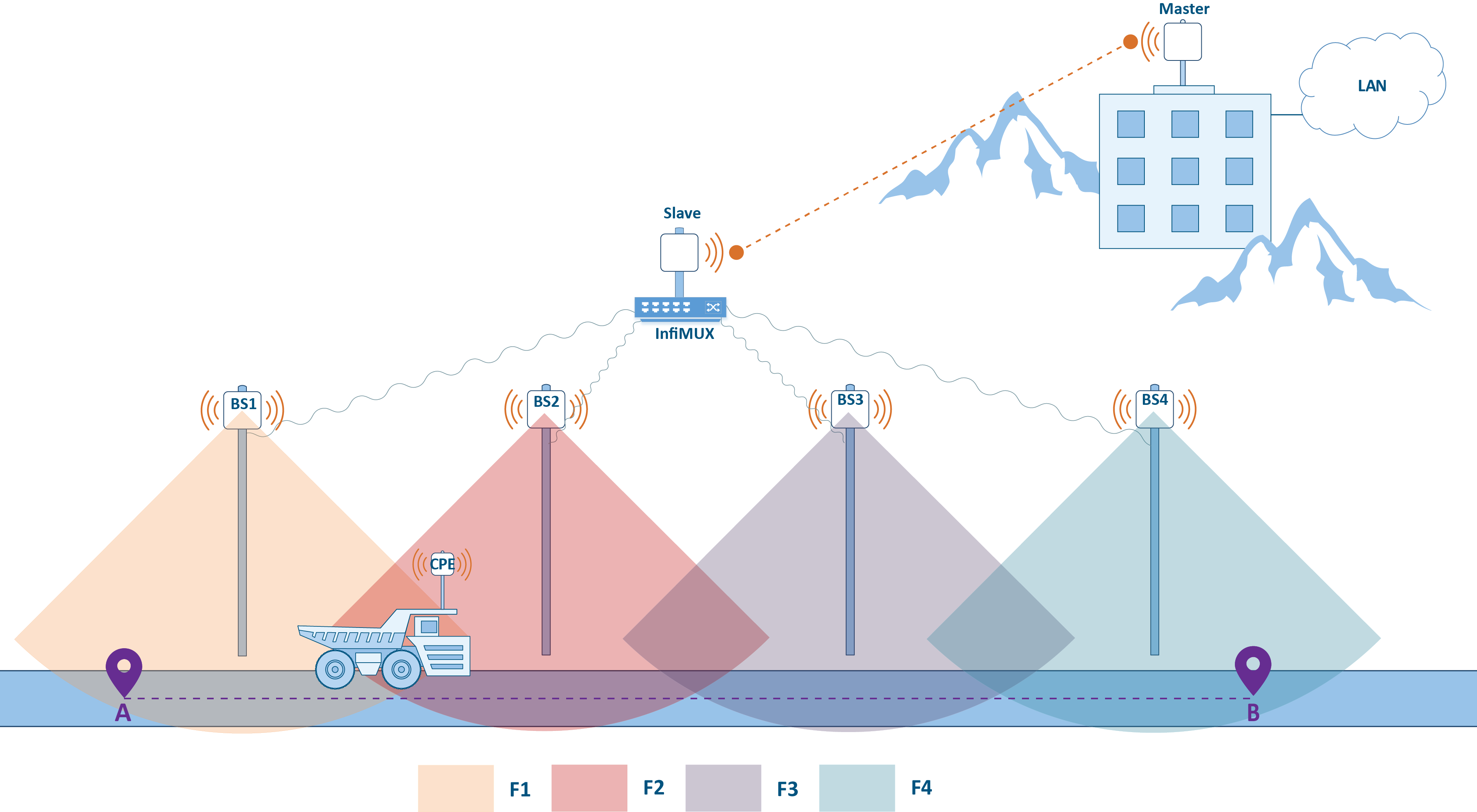
a)
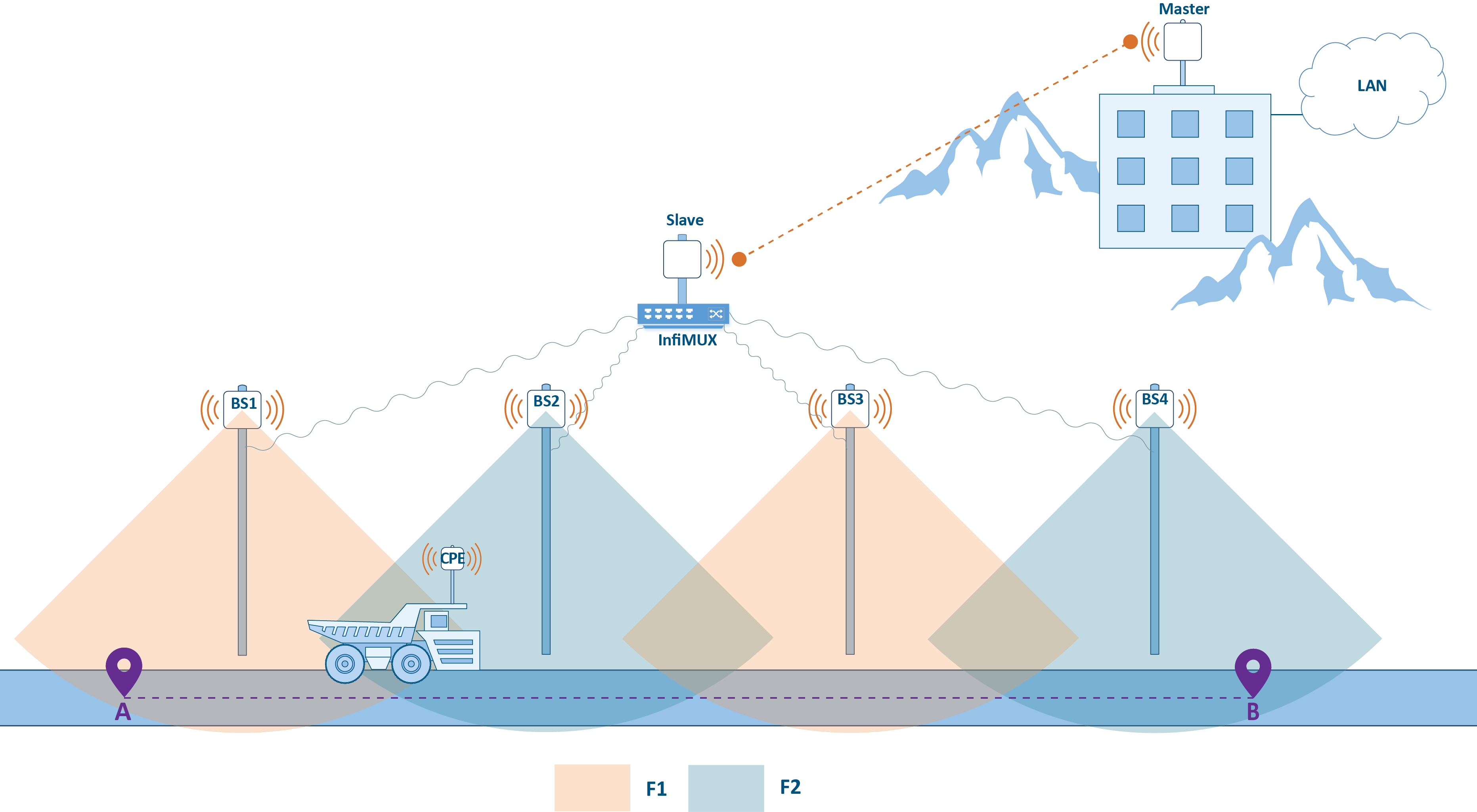
b)
Figure 3 - The allocation of frequency channels between BS: a - using four channels, b - using two channels
Device allocation
The position of the devices in space determines the actual quality indicators of the wireless link. The position of the devices is determined by the:
- Installation coordinates.
- Azimuth and antenna elevation.
- Suspension height.
In projects with mobile objects, the antenna's directional properties should be taken into account. If the BSs are static and the radio coverage area is constant, then the CPE's antenna radiation pattern can greatly affect the link quality. InfiNet's product portfolio includes devices with integrated antennas and the ability to connect external antennas as well. The selection of a specific device is determined by the specific requirements of the project.
The route profile must be evaluated along the entire trajectory of the object. This will allow to find potential "dead zones", with no connectivity with the mobile object. A decision to change the location of several base stations might be necessary in this case. In addition, perform a survey along the enterprise's territory, because the InfiPLANNER link planning tool does not take into account the effects of obstacles such as trees, buildings etc.
The InfiNet product portfolio includes a wide range of accessories, including mounting kits that allow to install devices in various conditions with the possibility of flexible alignment and the CAB-RV1 alignment tool which allows to perform preliminary device diagnostics.
The MINT protocol
The Ethernet link layer protocol was developed for the wired networks and does not take into account the specifics of the wireless environment. Wireless device manufacturers can use standard wireless protocols, such as Wi-Fi, or use their self-developed protocols. InfiNet Wireless has developed a proprietary data transfer protocol called MINT, especially designed for data exchange in a wireless environment.
MINT (Mesh Interconnection Network Technolohy) - InfiNet's proprietary technology used by the InfiLINK 2x2 and InfiMAN 2x2 family devices, provides data transfer between devices via wireless and wired links.
MINT area
One of the MINT protocol's main concepts is the MINT area. A MINT area consist of many neighboring devices and data exchange between them is carried out using MINT frames (check the "MINT protocol" lesson of the InfiLINK 2x2 and InfiMAN 2x2: Switching online course).
Let's look at the solution described below, that implements the MINT areas concept (see Figure 4). A radio link is installed between the Master and Slave devices, they form MINT 5 area. Each of the BS1, BS2, BS3, and BS4 sectors is potentially ready to establish a radio link with the CPE installed on the mobile object and form a separate MINT area with the corresponding identifier.
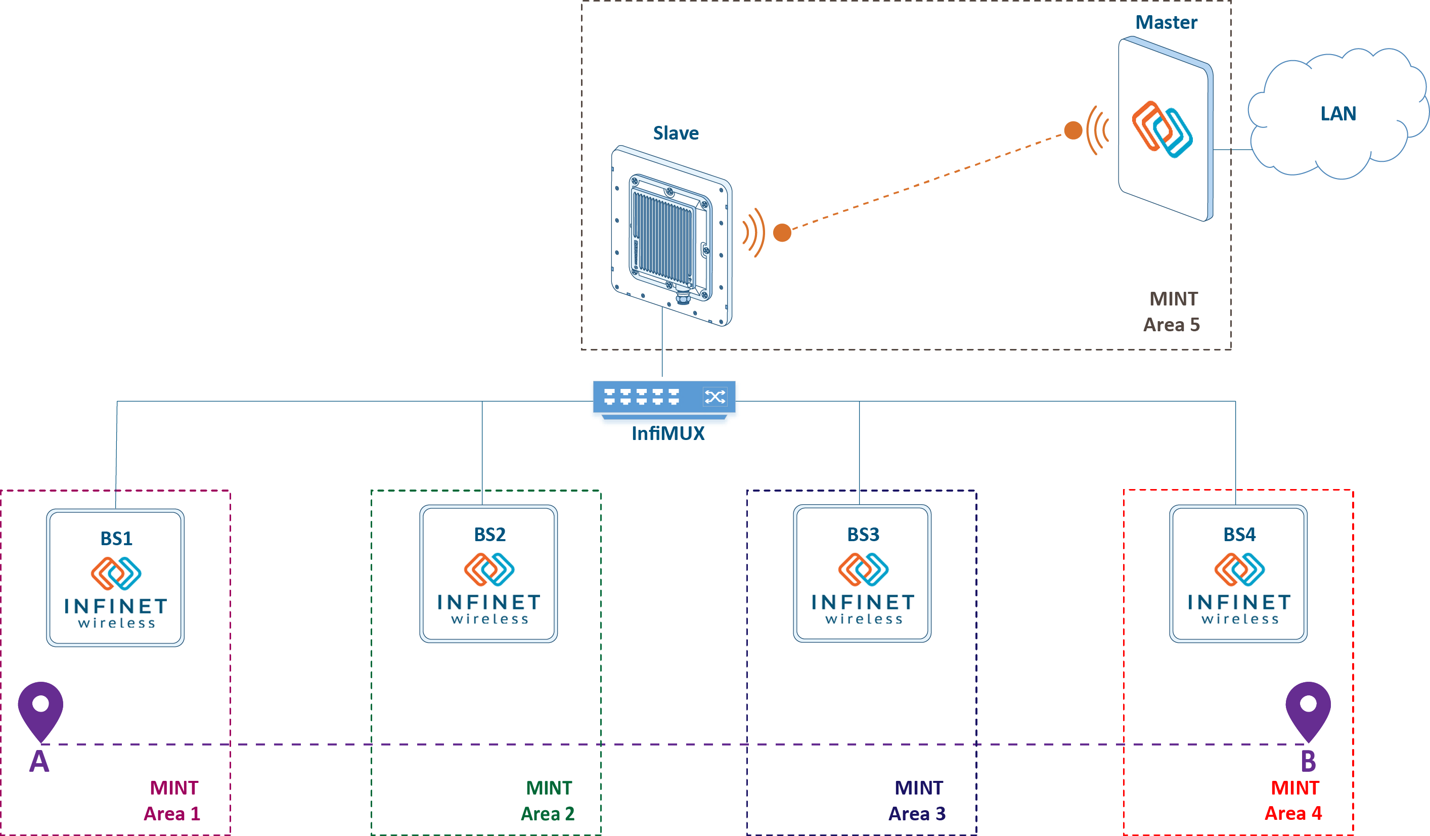
Figure 4 - Multiple MINT areas in the mobility scenario
Note that the MINT protocol is intended for data exchange within the MINT area. Data outside the MINT area can be transmitted using other protocols, such as Ethernet, i.e. the CPEs and each of the base stations are the gateway between the MINT and Ethernet networks. In our scheme, data is exchanged between a mobile object and a control center, i.e. the frame will go through several Ethernet segments and MINT areas in the forward and backward directions. Thus, switch group configuration on each device is a prerequisite for data transfer:
switch group 1 add eth0 rf5.0
switch group 1 start
switch start
In addition to encapsulating the Ethernet frames during the transmission through the MINT area, the MINT protocol performs an exchange of service messages to fill in the frame redirection table. The frame redirection table allows to select the frame transmission route (see video 5) through the MINT area in accordance with the radio parameters and the link load. This mechanism guarantees the selection of the route with the optimal radio parameters and prevents loops.
Video 1 - An example of route selection between nodes J and F in MINT
If necessary, you can influence the path selection algorithm by setting the link metric value manually. This can be done by summing the calculated and additional costs or by fixing a certain value (switching in InfiNet devices is described in the online course InfiLINK 2x2 and InfiMAN 2x2: Switching)
mint rf5.0 -extracost 1000
mint rf5.0 -fixedcost 1000
Data transfer and QoS configuration on each wireless device is a time-consuming task that can be simplified by extending the MINT area. The schemes intended to simplify the configuration of the wireless devices by joining them into a single MINT area, are shown below.
Joining sectors into one MINT area using InfiMUX
The main disadvantage of the solution above is the necessity to configure switch groups on all wireless devices. Since the switch group is a gateway between MINT and Ethernet, it is possible to combine all the BSs of the radio network into a single MINT area, transferring the gateway role to the InfiMUX switch (see Figure 5). In this case, a switch group has to be configured only on the InfiMUX. Joining devices into a single MINT area and the advantages of such a scheme are described in the InfiLINK 2x2 and InfiMAN 2x2: Switching online course.
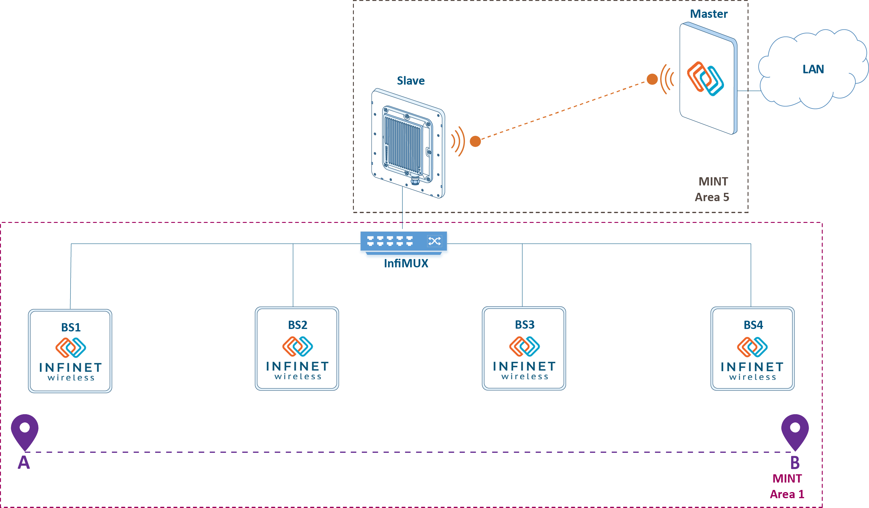
Figure 5 - Joining the backhaul radio network into a single MINT area
Using MINT protocol in a wired infrastructure is possible with PRF (pseudo radio) interface. It is a virtual interface that has a wired interface as a parent and encapsulates MINT frames in Ethernet frames. Configuration via CLI:
Create a PRF interface on a wireless device or InfiMUX:
Create PRF interfaceifc prf0 mtu 1500 up prf 0 parent eth0 hwmtu 1514 mint prf0 start
Join RF and PRF interfaces on the wureless device:
RF and PRF interfaces joiningmint join rf5.0 prf0
Join two PRF interfaces on InfiMUX:
Two PRF interfaces joiningmint join prf0 prf1
The advantages of such solution is the simplification of the QoS configuration, as traffic processing rules for different service classes are configured only on InfiMUX.
Joining sectors and the backbone link in one MINT area
The disadvantage of the scheme with backbone radio network devices joining in a single MINT area is the quality of service policy complication: the used traffic classification rules must be duplicated on InfiMUX and on the Master and Slave devices. If these rules are not duplicated, the effect of QoS policy implementation can be significantly reduced.
One of the solutions is to combine the channel-forming devices of the link into a single area with all other devices (see Figure 6). This solution is realizable only when using InfiLINK 2x2 family devices on the backbone link. In this case, the unified traffic classification rules configured on the Master device will be valid in the entire MINT area. In addition, the gateway functions between MINT and Ethernet can be transferred to the Master device, any switch can be used instead of InfiMUX. Areas joining is carried out similar way as the above configuration.
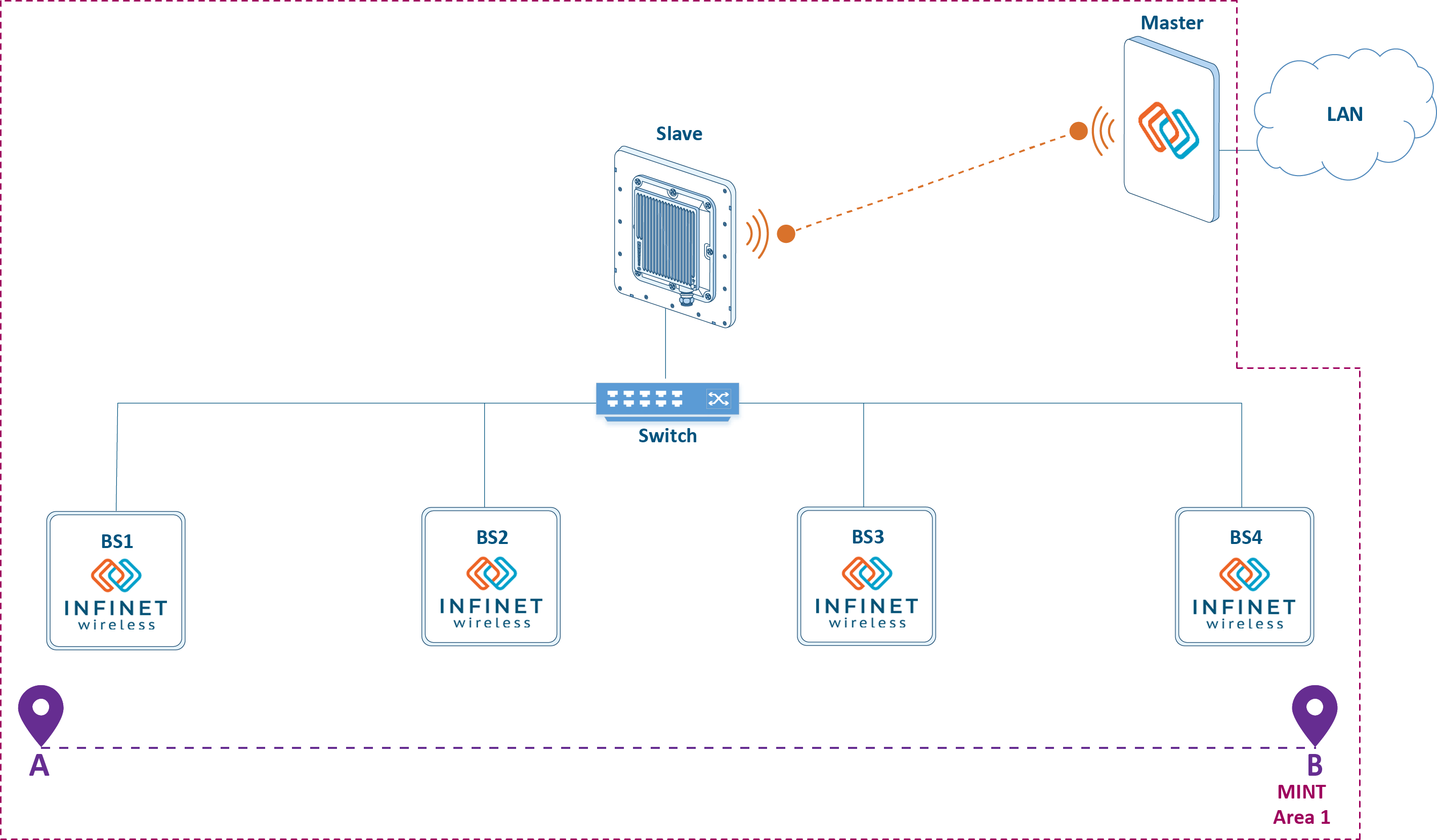
Figure 6 - Joining all wireless devices in a single MINT area
Roaming
The movement of the mobile object with CPE installed, within the backbone radio network is accompanied by a transition from the coverage area of one BS sector to another sector coverage area of same or another BS. The CPE transition process between BS sectors is called roaming. Roaming is accompanied with radio link brake with the first sector and the connection establishment with the second sector.
Let's look at the roaming mechanism (see video 2):#min_max
- There is a radio link between CPE and BS1.
- The vehicle moves and the radio link between CPE and BS1 breaks. The reason is the inability to maintain communication due to insufficient signal energy. As it is shown below, the breakage initiator of the radio link can be both CPE and the corresponding sector BS1.
- The CPE is trying to reconnect to BS1. If successful, the algorithm returns to step 1; if not - to step 4.
- The CPE searches for devices to establish the radio connection.
- CPE finds out BS2 and tries to establish a connection with it.
- CPE establishes a radio link with BS2.
Video 2 - Roaming mechanism
Radio link establishing
A radio link can be established between two devices if the following requirements are met:
- At least one device has a Master role. Possible connections: Master-Master, Master-Slave. The solution architecture suppose configuration of BS sectors as Masters, and CPEs as slaves.
- A radio profile has been created in CPE configuration, corresponding to the radio settings on the BS.
- Signal parameters (RSSI, SNR, etc.) allow data exchange at least at the minimal modulation.
Radio profiles
On Master devices, only one set of radio parameters can be configured, which will be used to establish links. On Slave devices, several radio profiles can be created, or one with the ability to automatically select a frequency. Configuration via CLI:
Configure radio parameters on the Master device:
Frequency configuration on the Masterrf rf5.0 band 20 rf rf5.0 mimo greenfield rf rf5.0 freq 5510 bitr 130000 sid 10101010 burst rf rf5.0 txpwr auto pwrctl distance auto
Create a radio profile on the Slave device with a fixed frequency value:
Radio profile with fixed frequencymint rf5.0 prof 1 -band 20 -freq 5510 -sid 10101010 \ -nodeid 60755 -type slave \ -autobitr -mimo greenfield
Create a radio profile on the Slave device with automatic frequency selection (if a profile with a fixed frequency value is used, the command below will not be executed):
Radio profile with automatic frequency selectionmint rf5.0 prof 1 -band 20 -freq auto -sid 10101010 \ -nodeid 60755 -type slave \ -autobitr -mimo greenfield
When Slave device tries to establish a connection, it cyclicaly look over the radio profiles added to its configuration. As soon as one of the profiles became suitable for a link establishment with the master device, starts the connection and the profile search is stopped. In case a profile with automatic frequency selection is created, the Slave device tries to establish a connection with the Master by searching through the frequencies supported by the radio module. The list of frequencies to search through may be limited by the configuration of the user frequency grid.
Example of a custom frequency grid configuration via CLI (for the rf5.0 interface, the frequency range from 5000 MHz to 5100 MHz with a step of 10 MHz is set, which can be used as the center link frequency with a channel width of 20 MHz):
rf rf5.0 grid 20 5000-5100/10
Obviously, link establishing can be a longtime operation when the automatic frequency selection mode is used due to the wide range of frequencies supported by the radio module. It is unacceptable in scenarios with roaming, therefore, we recommend to create separate radio profiles for each BS sector of the backbone radio network in CPE configuration.
Dynamic frequency selection
Master devices same as a Slave, support the dynamic frequency selection (DFS) mode. Devices with DFS support, before selecting a frequency, scan the available frequency channels, evaluate the interference level and the radars presence. Operation channel is selected among the frequency channels free of radar, with a minimum interference level.
DFS is a standard technology for wireless devices, the disadvantage is that the assessment of the radio environment is performed only at the start and is not updated during operation. Using an additional radio module on some models of InfiNet devices allows to implement proprietary Instant DFS technology. An additional radio module constantly scans the air, performing a transition between frequency channels in accordance with the interference level. DFS, Radar detection, and Instant DFS technologies are detaily described in the Dynamic Frequency Selection document.
DFS configuration via CLI:
Enable DFS on the Master device:
DFS enabledfs rf5.0 dfsonly dfs rf5.0 freq auto
Enable DFS and Radar detection on the Master device:
DFS and Radar detection enabledfs rf5.0 dfsradar dfs rf5.0 freq auto
Enable iDFS support on the Master and Slave devices:
iDFS enablemint rf5.0 -idfs
Frequency roaming
In this document frequency roaming is a change of the link operating frequency, i.e. frequency change is performed on both devices.
The frequency roaming mechanism operation is closely related to the Instant DFS function, when frequency channels with a lower interference level is detected, the BS sector in PtMP mode or Master in PtP mode must change the operating frequency. At the same time, the devices connected to them must also change the frequency channel. The devices behavior during frequency roaming is determined by the "roaming" parameter value:
- leader: the device set a new frequency channel and sends service messages to other devices to change the operating frequency. We recommend to configure this function on a device with the DFS / iDFS function enabled.
- enable: the device, having received a command to change the operating frequency from the "leader", performs the transition to a new frequency channel.
- disable: the device, having received a command to change the operating frequency from the "leader", ignores it.
This solution does not use DFS technology, however, in projects where the use of DFS / iDFS is necessary, it is advisable to configure the BS sectors as "roaming leader", and CPE as "roaming enable".
Configuration via CLI:
Enable roaming on the Master device:
BS sector configurationmint rf5.0 roaming leader
Enable roaming on the Slave device:
CPE configurationmint rf5.0 roaming enable
Restart rf5.0 interface on both devices
BS and CPE configurationmint rf5.0 restart
Note that a Slave device with "roaming enable", having received a command to change the operating frequency from the "roaming leader", will switch to another frequency channel even if there is no corresponding radio profile in the Slave device configuration. In this case, after a reboot, the slave will not be able to establish a link, because will be guided by a set of radio profiles added to the configuration.
MultiBS function
The main disadvantage of the roaming mechanism is that CPE, after breaking the link with BS1, tries to restore this connection and, only after several unsuccessful attempts, searches for other BSs to establish the new connection. InfiNet devices support the proprietary MultiBS function, which speed up this process.
The roaming mechanism with the MultiBS function is presented below (see video 3):
- Link is established between BS1 and CPE.
- The vehicle moves and the radio link parameters between CPE and BS1 deteriorate. CPE breaks the connection with BS1. Despite the fact that the radio link between CPE and BS1 can be used to transmit data, CPE notice a negative trend and preventively breaks the connection.
- CPE searches for devices to establish a connection.
- CPE finds out one of the BS2 sectors and tries to establish a link with this device.
- CPE establishes a radio link with one of the BS2 sectors.
Video 3 - Roaming mechanism with MultiBS function
Run the following command to enable MultiBS function:
mint rf5.0 roaming enable multiBS
Global function
Let's look at the scenario in which the cable route between the InfiMUX and the BS1 power injector was damaged (see Figure 7), i.e. power is supplied to BS1 and the device is ready to establish radio connections, but data can not be transmitted to the control center.
The vehicle with CPE starts moving along the trajectory from point A to point B. Being in the BS1 coverage area CPE establishes a radio link with it. Since the cable route is damaged, no data is transmitted between the moving object and the control center. Moving along the trajectory, the mobile object get in the area when it is possible to connect to BS2, but the connection parameters with BS1 are satisfactory and the CPE does not perform roaming between the BS. Without the configured MultiBS function, the CPE will keep connection with the BS1 sector until leaves its radio coverage area.
Global proprietary feature avoids this situation. If the Global function is activated on CPE, then CPE will establish a radio link only with devices there the Global function is also enabled. In addition, devices in the same MINT area can perform a proxy function for devices with the Global function enabled. Thus, if the Global function is enabled on the InfiMUX and CPE, then all BSs will inform CPE that they have a connection to InfiMUX with Global function activated at the time the connection is established. If a cable route is damaged between BS1 and InfiMUX, BS1 will not inform the CPE about the availability of InfiMUX, i.e. the speaker will not establish a radio link with BS1.
Using the Global function allows to increase the fault tolerance of the backbone radio network, however, it will have an effect only with appropriate radio frequency planning - the coverage areas of the sectors must be overlapped.
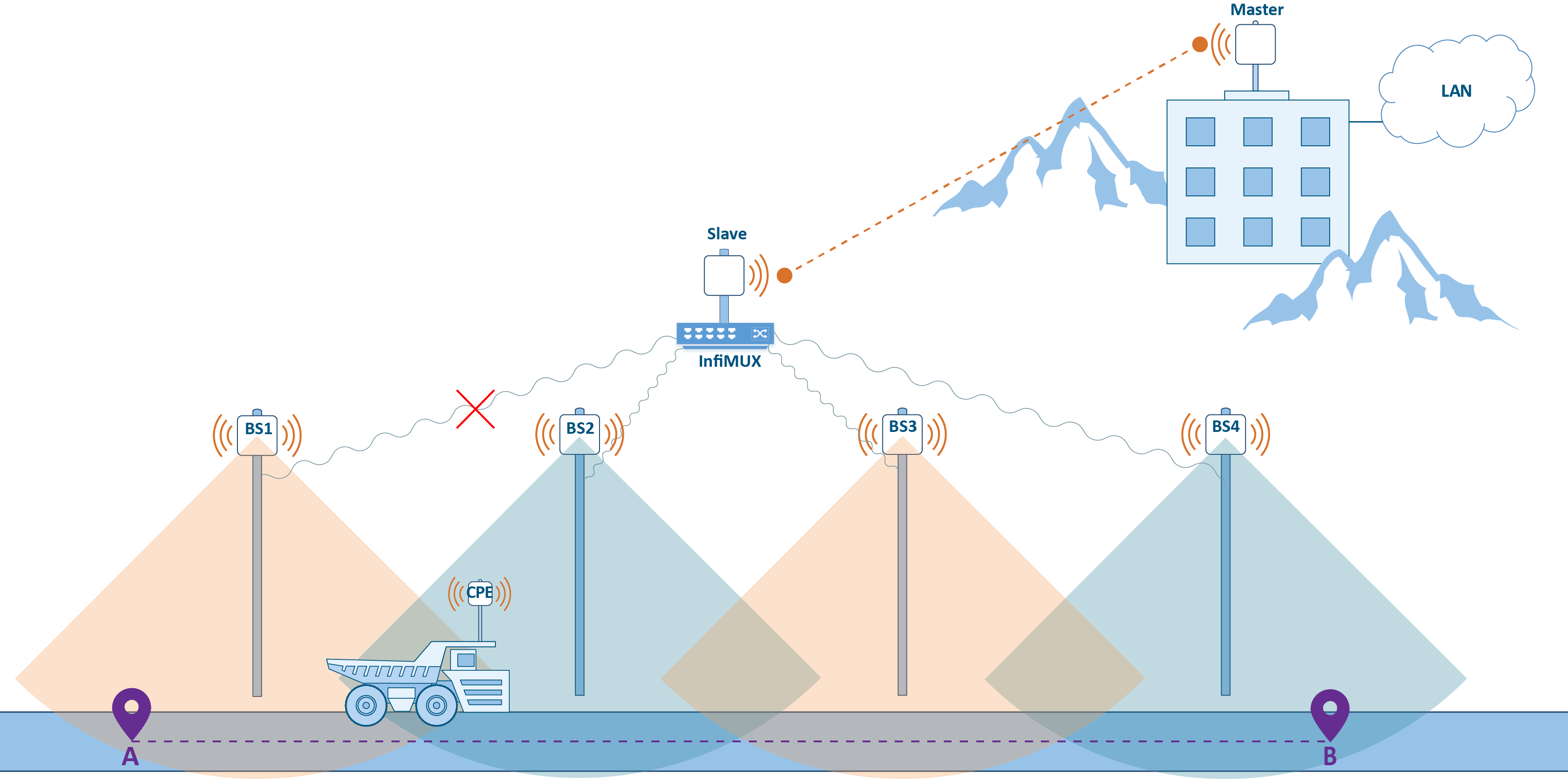
Figure 7 - Global function using
Device configuration via CLI:
Enable Global function on CPE:
Global function on CPEmint rf5.0 roaming enable global
Enable Global function on InfiMUX:
Global function on InfiMUXmint prf0 roaming enable global
Link establishment process control
One of the mechanisms determining the moment of disconnection from one sector and establishing connection with another is the assessment SNR values threshold. Two thresholds are used in a wireless device configuration:
- hiamp: minimum SNR value required to establish a radio link between two devices.
- loamp: minimum SNR value at which the radio link between devices will not be broken.
Thus, threshold values configuration on a BS or CPE is the mechanisms for controlling the process of CPE roaming.
The SNR level configuration for establishing a radio link on wireless devices is performed using the following commands:
mint rf5.0 -hiamp 2
mint rf5.0 -loamp 0
Fixed/mobile/nomadic modes
One of the factors affecting the link parameters with a moving object is the relevance of the MINT frame redirection table. This configuration can only be applied on the InfiLINK 2x2 and InfiMAN 2x2 families devices. Device configuration allows to set the update interval for the MINT redirection table entries by choosing one of the three "mode" parameter values:
- fixed: redirection table is updated at intervals of 3 seconds. This mode is intended for the static link organization.
- nomadic: redirection table is updated at intervals of 1,5 seconds. This mode is intended for the link organization with slowly moving objects.
- mobile: redirection table is updated at intervals of 1 second. This mode is intended for the link organization with mobile objects.
As shown above, CPE with activated MultiBS function compares the current radio link performance with the maximum achieved. There is a possible scenario in which the radio link parameters deteriorate sharply due to the short-term influence of the interference and also recover sharply. CPE will break the connection with the BS in accordance with the MultiBS function algorithm, despite the fact that the radio link parameters deterioration had a short-term nature. The “mode” parameter selection affects the radio parameters analysis when the MultiBS function is enabled by setting the evaluation time interval. Thus, a device in a fixed mode evaluates the radio parameters over an three seconds interval and is more resistant to link rupture under short-term interference than a device in a mobile mode..
Mode parameter in the device can be configured by following commands:
Set fixed mode on the Master and Slave devices:
Fixed mode configurationmint rf5.0 -mode fixed
Set nomadic mode on the Master and Slave devices:
Nomadic mode configurationmint rf5.0 -mode nomadic
Set mobile mode on the Master and Slave devices:
Mobile mode configurationmint rf5.0 -mode mobile
Using two subscriber devices at the object
As shown above, MultiBS function speeds up the CPE roaming between the BSs, however, in any case, roaming is accompanied by a short break in connection. Link interruption avoidance can be reached by using two CPEs on a moving object, combined by InfiMUX. In this case, each CPE will independently establish a radio link with the BS, and InfiMUX will distribute data traffic between those links.
Let's look at the roaming algorithm with two CPEs (see Figure 8):
- CPE1 and CPE2 have established links with BS. In this case, no loop appears because all radio devices are joined in one MINT area and devices use a frame redirection table that takes into account the cost parameters.
- The vehicle is moving, CPE2 breaks the link with BS1. CPE1 keeps connection with BS1. Service hasn't been interrupted, because the data exchange between the vehicle and the control center is carried out via CPE1-BS1 link.
- CPE2 is looking for for a BS to establish a radio link. CPE1 keeps connection with BS1.
- CPE2 establishes connection with BS2. CPE1 keeps connection with BS1. When transmitting data, InfiMUX uses one of the two links CPE1-BS1 and CPE2-BS2, with a lower metric.
- The vehicle is moving, CPE1 breaks the link with BS1. CPE2 keeps connection with BS2. Data transmission is performed via CPE2-BS2, link, service hasn't been interrupted.
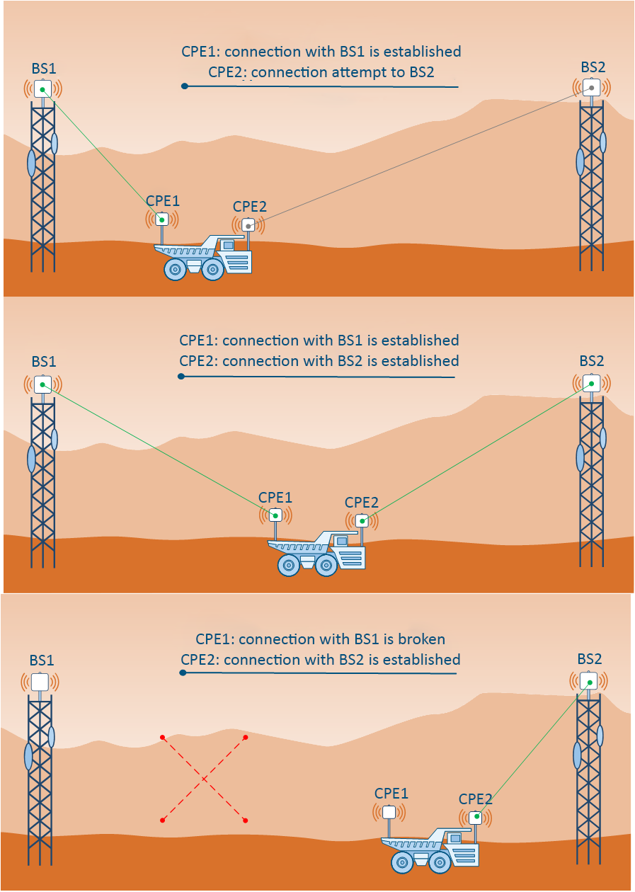
FIgure 8 - Roaming with two CPEs on a mobile object
To make configuration, PRF interfaces should be created on CPE1 and CPE2 devices towards InfiMUX, and on InfiMUX - PRF interfaces towards wireless devices. In addition, the switch groups configuration must be performed on the InfiMUX, not on the CPEs.
Keep in mind that any changes in the configuration from the command line, should be saved. The command to save configuration:
config save
Additional materials
Online courses
- Wireless Networking Fundamentals.
- InfiPLANNER: Link Planning Tool.
- InfiLINK 2x2 and InfiMAN 2x2: Switching.
White papers
- Performance of the InfiNet Wireless devices.
- Link aggregation, balancing and redundancy.
- TDMA and Polling: Application features
- Dynamic Frequency Selection.
Webinars
- InfiNet Wireless equipment installation, grounding and lightning protection.
- Switching configuration using InfiNet Wireless devices - typical scenarios.
- InfiNet Wireless PtMP network design with frequency reuse and SYNC.