...
| Center |
|---|
Figure 5 - Joining the backhaul radio network into a single MINT area |
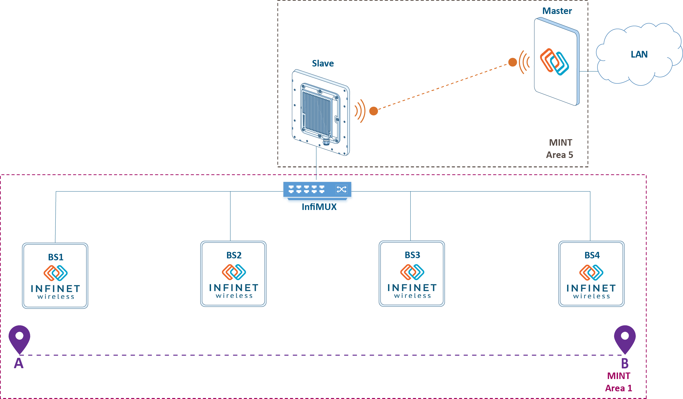
Using the MINT protocol in a wired infrastructure is possible with the help of the PRF (pseudo radio) interface. It is a virtual interface that has a wired interface as a parent and encapsulates MINT frames in Ethernet framesit encapsulates Ethernet frames into MINT frames. Configuration via CLI:
Create a PRF interface on a wireless device or InfiMUXon the InfiMUX:
Code Block language text theme Emacs title Create PRF interface ifc prf0 mtu 1500 up prf 0 parent eth0 hwmtu 1514 mint prf0 start
Join RF and PRF interfaces on the wureless wireless device:
Code Block language text theme Emacs title RF and PRF interfaces joining mint join rf5.0 prf0
Join two PRF interfaces on InfiMUXthe InfiMUX:
Code Block language text theme Emacs title Two PRF interfaces joining mint join prf0 prf1
The advantages of such a solution is the simplification of the QoS configuration, as traffic processing rules for different service classes are configured only on the InfiMUX.
Joining sectors and the backbone link
...
into one MINT area
The disadvantage of the scheme with backbone having the backhaul radio network devices joining in joined into a single MINT area is the quality of service policy complicationthat needs to be implemented at the backbone devices as well: the used traffic classification rules must be duplicated on the InfiMUX and on the Master and Slave devices. If these rules are not duplicated, the effect of the QoS policy implementation can be significantly reduced.
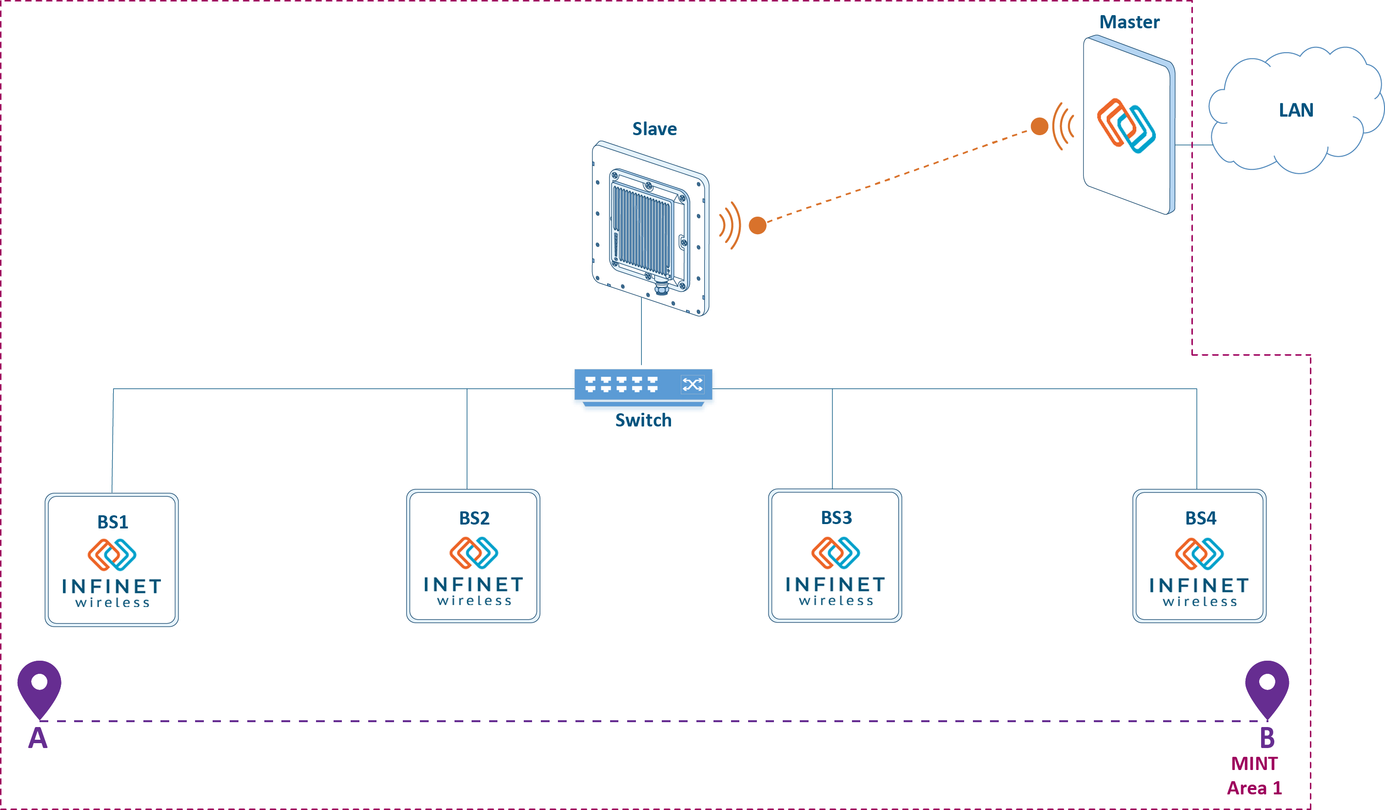
One of the solutions is to combine the channel-forming devices of the link backbone link into a single area with all the other devices (see Figure 6). This solution is realizable is possible only when using InfiLINK 2x2 family devices on devices for the backbone link. In this case, the unified traffic classification rules configured on the Master device will be valid in the entire MINT area. In addition, the gateway functions between MINT and Ethernet can be transferred to the Master device, while any switch can be used instead of InfiMUX. Areas joining is carried out similar way as the above configuration.
| Center |
|---|
Figure 6 - Joining all wireless devices in into a single MINT area |
Roaming
The movement of the mobile object, with the CPE installed on top, within within the backbone access radio network is accompanied by a transition from the coverage area of one BS sector to another sector's coverage area of the same or of another BS. The CPE transition process of the CPE between BS the BS sectors is called roaming. Roaming is accompanied with radio link brake Roaming implies the disconnection of the radio link with the first sector and the connection establishment with the second sector.
...
- There is a radio link between the CPE and BS1.
- The vehicle moves and the radio link between CPE and BS1 breaksbecomes unavailable. The reason is the inability to maintain the communication due to insufficient signal energypower. As it is shown below, the breakage initiator of the radio link can be both CPE and disconnection can be either the CPE or the corresponding sector BS1of BS1.
- The CPE is trying to reconnect to BS1. If successful, the algorithm returns to step 1; if not - to step 4.
- The CPE searches for devices to establish the radio connection.
- The CPE finds out BS2 and tries to establish a connection with it.
- The CPE establishes a radio link with BS2.
| Center | ||||||||
|---|---|---|---|---|---|---|---|---|
Video 2 - Roaming mechanism |
Radio link
...
establishment
A radio link can be established between two devices if the following requirements are met:
- At least one device of the devices has a Master role. Possible connections: Master-Master, Master-Slave. The solution architecture suppose configuration architecture implies the configuration of the BS sectors as Masters , and of the CPEs as slavesSlaves.
- A radio profile has been created in CPE the CPE configuration, corresponding to the radio settings on the settings of the BS.
- Signal The signal parameters (RSSI, SNR, etc.) allow data the data exchange at least at the minimal modulation.
...
On Master devices, only one set of radio parameters can be configured, which will be used to establish the links. On Slave devices, several radio profiles can be created, or only one with , but with the ability to automatically select a frequency. Configuration via CLI:
Configure the radio parameters on the Master device:
Code Block language text theme Emacs title Frequency configuration on the Master rf rf5.0 band 20 rf rf5.0 mimo greenfield rf rf5.0 freq 5510 bitr 130000 sid 10101010 burst rf rf5.0 txpwr auto pwrctl distance auto
...
Create a radio profile on the Slave device with automatic frequency selection (if a profile with a fixed frequency value is used, the command below will not be executed):
Code Block language text theme Emacs title Radio profile with automatic frequency selection mint rf5.0 prof 1 -band 20 -freq auto -sid 10101010 \ -nodeid 60755 -type slave \ -autobitr -mimo greenfield
When the Slave device tries to establish a connection, it cyclicaly look looks over the radio profiles added to its configuration. As soon as one of the profiles became becomes suitable for a link establishment with the master Master device, starts it initiates the connection and the profile search is stopped. In case that a profile with automatic frequency selection is createdused, the Slave device tries to establish a connection with the Master by searching through the frequencies supported by the radio module. The list of frequencies to search through may be limited by the configuration of the user frequency grid.
Example of a custom frequency grid configuration via CLI (for the rf5.0 interface, the frequency range from 5000 MHz to 5100 MHz with a step of 10 MHz is set, which can be used as the center link frequency with when using a channel width of 20 MHz):
...
Obviously, link establishing can be a longtime operation when the automatic frequency selection mode is used due to the wide range of frequencies supported by the radio module. It is unacceptable in scenarios with roaming, therefore, we recommend to create create on the CPE separate radio profiles for each BS sector of the backbone backhauling radio network in CPE configuration.
Dynamic frequency selection
Master devices same as well as a Slave devices, support the dynamic frequency selection (DFS) mode. Devices with DFS support, before Before selecting a frequency, scan the devices with DFS support scan the available frequency channelsrange, evaluate the interference level and the radars presence of radar. Operation The operational channel is selected among the frequency channels free of radar, with having a minimum interference level.
DFS is a standard technology for wireless devices, but the disadvantage is that the assessment of the radio environment is performed only at the start and is not updated during only in the beginning and no updates are performed during operation. Using an additional radio module, on some models of InfiNet devices, allows to implement the proprietary Instant DFS technology. An additional radio module constantly scans the air, performing a transition a swap between frequency channels in accordance with the interference level. DFSlevels in real time. The DFS, Radar detection , and Instant DFS technologies are detaily described in the Dynamic Frequency Selection document.
...
Enable DFS on the Master device:
Code Block language text theme Emacs title DFS enable dfs rf5.0 dfsonly dfs rf5.0 freq auto
Enable DFS and Radar detection on the Master device:
Code Block language text theme Emacs title DFS and Radar detection enable dfs rf5.0 dfsradar dfs rf5.0 freq auto
Enable iDFS Enable the iDFS support on the Master and Slave devices:
Code Block language text theme Emacs title iDFS enable mint rf5.0 -idfs
...
In this document frequency roaming is a change roaming represents a change in the operating frequency of the link operating frequency, i.e. the frequency change is performed on both devices.
The frequency roaming mechanism operation is closely related to the Instant DFS function, when frequency channels . When a frequency channel with a lower interference level is detected, the BS sector in PtMP mode or the Master in PtP mode must change the operating frequency. At the same time, the devices connected to them must also change the frequency channel. The devices behavior during The behavior during frequency roaming is determined by the "roaming" parameter value:
- leader: the device set sets a new frequency channel and sends service messages to other devices to change the their operating frequency as well. We recommend to configure this function on a device with the DFS / iDFS function enabled.
- enable: the device, having received a command to change the operating frequency from the "leader", performs the transition to a new frequency channel.
- disable: the device, having received a command to change the operating frequency from the "leader", ignores it.
This solution does not use the DFS technology, however, in projects where the use of DFS / iDFS is necessary, it is advisable to configure the BS sectors as "roaming leader" , and CPE the CPEs as "roaming enable".
Configuration via CLI:
Enable roaming on the Master device:
Code Block language text theme Emacs title BS sector configuration mint rf5.0 roaming leader
Enable roaming on the Slave device:
Code Block language text theme Emacs title CPE configuration mint rf5.0 roaming enable
Restart the rf5.0 interface on both devices
Code Block language text theme Emacs title BS and CPE configuration mint rf5.0 restart
Note that a Slave device with "roaming enable", having received a command to change the operating frequency from the "roaming leader", will switch to another frequency channel even if there is no corresponding radio profile in the Slave device configuration. In this case, after a reboot, the slave will not be able to establish a link, because it will still be guided by a by the set of radio profiles added to the configuration.
| Anchor | ||||
|---|---|---|---|---|
|
...
The MultiBS function
The main disadvantage of the roaming mechanism is that the CPE, after breaking the link with BS1, tries to restore this connection and , only after several unsuccessful attempts, searches for other BSs to establish the establish a new connection. InfiNet devices support the proprietary MultiBS function, which speed speeds up this process.
The roaming mechanism with the MultiBS function is presented below (see video 3):
- Link The link is established between BS1 and the CPE.
- The vehicle moves and the radio link parameters between the CPE and BS1 deteriorate. CPE breaks The CPE interrupts the connection with BS1. Despite the fact that the radio link between the CPE and BS1 can be used to transmit data, CPE notice the CPE notices a negative trend and preventively breaks the connection.
- The CPE searches for devices to establish a connection.
- CPE finds out The CPE senses one of the BS2 sectors and on BS2 and tries to establish a link with this device.
- The CPE establishes a radio link with one of the BS2 sectors.
...
Run the following command to enable the MultiBS function:
| Code Block | ||||||
|---|---|---|---|---|---|---|
| ||||||
mint rf5.0 roaming enable multiBS |
...
The global function
Let's look at the scenario in which the cable route between the InfiMUX and the BS1 power injector was damaged (see Figure 7), i.e. power is supplied to BS1 and the device is ready to establish radio connections, but data can not be transmitted to the control center.
...