The switch page allows you to configure the ports of the unit and the switching related features.
| Center |
|---|
Please make the distinction between the internal "RADIO" port of the Ethernet switch used for the data path separation and the external "RADIO" port of the unit.| Scroll Title |
|---|
| title | Figure- InfiLINK XG block diagram |
|---|
| 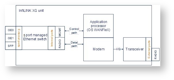 Image Removed Image Removed
|
|
| Note |
|---|
|
| 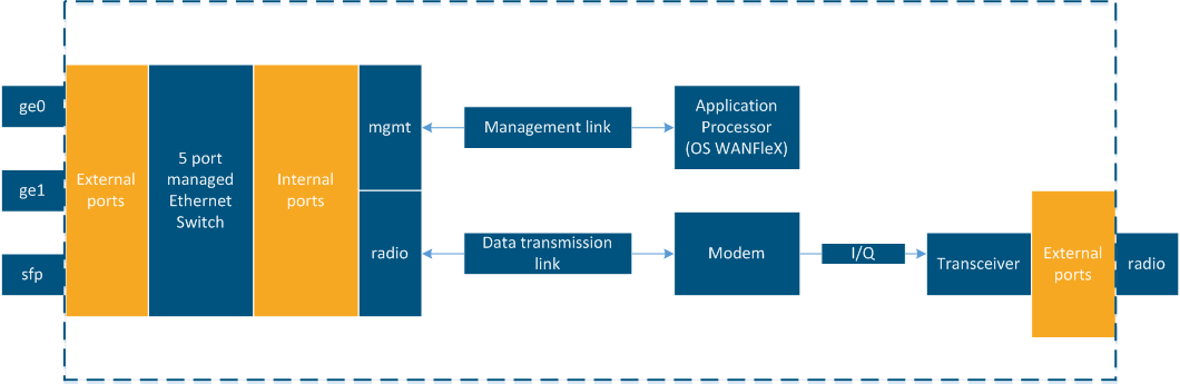 Image Added Image Added
|
|
The following 5 ports are available
...
at the unit:
- "GE0ge0" and "GE1ge1" ports - external copper Gigabit Ethernet ports 1000BASE-T (IEEE 802.1ab).
- "SFPsfp" port - external optical Gigabit port for plugging of the optical SFP transceiver module.
- "RADIOradio" port - internal radio interface of the device.
- "MGMTmgmt" port - internal interface for the device management.
The switch page has four sections:
- "Switch Port Settings"
- "Port Interconnection Schema"
- "Connectivity matrix"
- "VLAN-based Switching"
| Center |
|---|
| Scroll Title |
|---|
| title | Figure - Switch section |
|---|
| 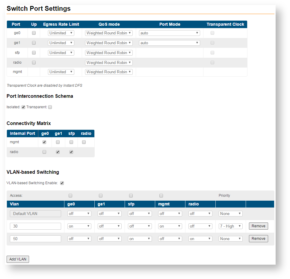 Image Removed Image Removed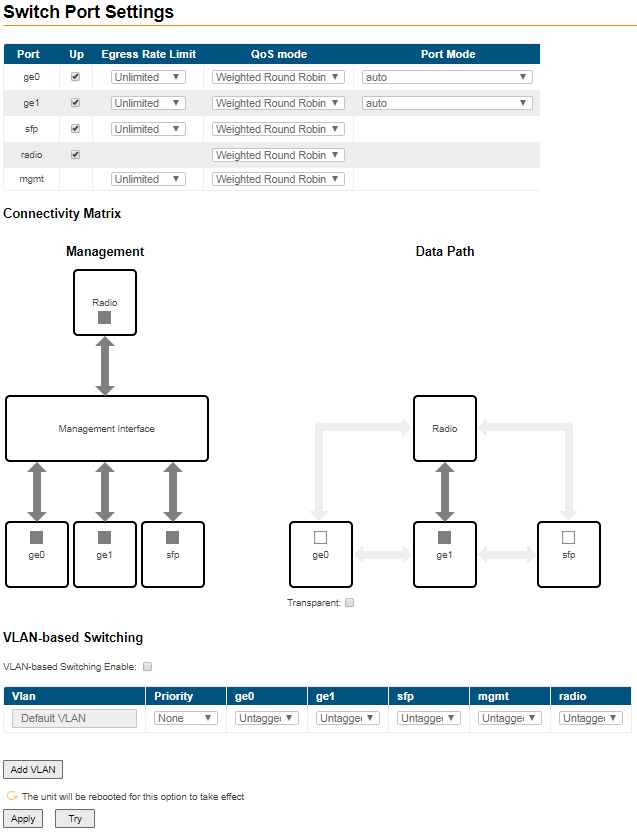 Image Added Image Added
|
|
- "Switch Port Settings" - allows you to perform general port configuration.
| Center |
|---|
| Scroll Title |
|---|
| title | Figure - Switch Port Settings |
|---|
| 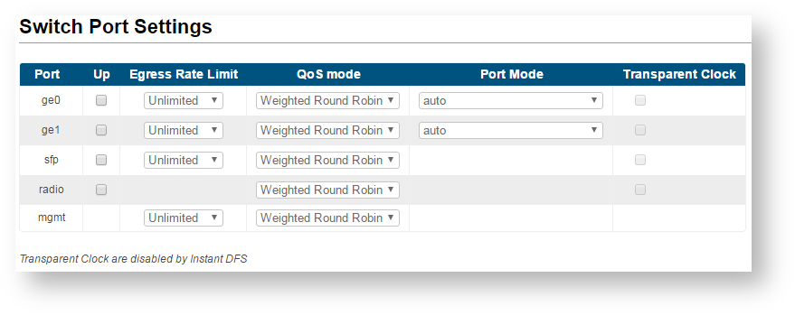 Image Removed Image Removed
|
|
The following port parameters can be customized:
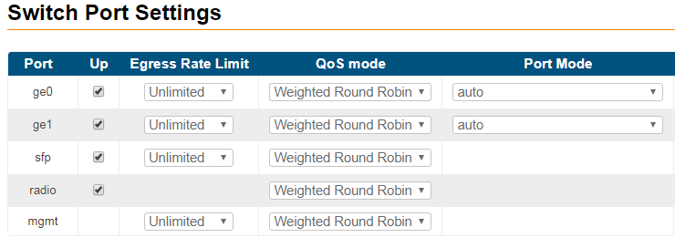 Image Added Image Added
|
|
| Center |
|---|
| Scroll Title |
|---|
| title | Table - Port parameters |
|---|
| | Parameter | Description |
|---|
| Up | - You can enable or disable the port status
| | Egress Rate Limit | - You can set the limit (traffic shaper) on the selected port, for outgoing traffic, in Mbps, from 1 to 100 in increments of 1, from 100 to 1000 in increments of 10, or to set it unlimited
| | QoS mode | - You can select the traffic shaper policy for the port, WRR is selected by default
|
“Weighted Robin” - Robin” - weights are used for every queue of an interface, which allows different queues to have different service shares depending on the weight value
|
“Strict” - “Strict” - packets within lower priority queue are not processed if the higher priority queue is not empty
| | Port Mode | - You can select the physical port operational mode from:
- auto: the speed and operational mode of the port will be negotiated between the 2 end points
- 10BaseT-halfduplex;10BaseT-halfduplexmanual; 10BaseT-fullduplex;10BaseT-fullduplex-manual
- 100BaseTX-halfduplex; 100BaseTX-halfduplex-manual; 100BaseTX-fullduplex; 100BaseTX-fullduplex-manual
- 1000BaseTX-fullduplex;1000BaseTX-fullduplex-manual
|
Transparent Clock- You can enable or disable synchronization clock in accordance with Precision Time Protocol (IEEE 1588)
| |
|
| Note |
|---|
|
Manual settings for the "Port Mode" will disable the negotiation and detection for speed and duplex. Use them in case that the interconnected 3rd party switches have fixed speed and duplex settings. |
...
...
...
| Center |
|---|
| Scroll Title |
|---|
| title | Figure - Port Interconnection Schema |
|---|
|  Image Removed Image Removed
|
|
- The "Connectivity matrix"Connectivity Matrix" allows you to enable or disable switching between internal and external ports of the switch.
| Center |
|---|
| Scroll Title |
|---|
| title | Figure - Connectivity matrix |
|---|
| 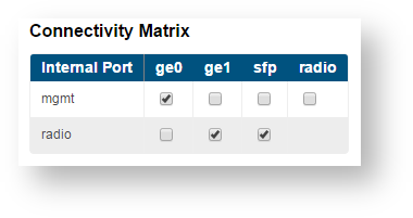 Image Removed Image Removed
|
|
For example, it is quite easy to disable management of the unit via wireless link just by disabling check box between “mgmt” and “radio” ports. Example shown below
| Center |
|---|
| Scroll Title |
|---|
| title | Figure - Connectivity matrix section example |
|---|
|  Image Removed Image Removed
|
|
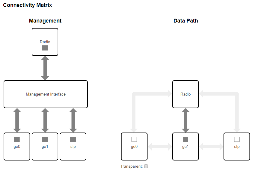 Image Added Image Added
|
|
In "Transparent" mode packet switching is allowed between external and internal ports, in case of VLAN-based Switching enabled switching is performed by VLAN tags.
- "VLAN-based Switching" allows to create list of allowed VLANs and their handling on InfiLINK XG switch on the unit switch plane. Without such option active, wireless link works as transparent Layer 2 bridge. Thus, the link transport any frames with any VLAN tags set.
| Center |
|---|
| Scroll Title |
|---|
| title | Figure - VLAN-based Switching |
|---|
| 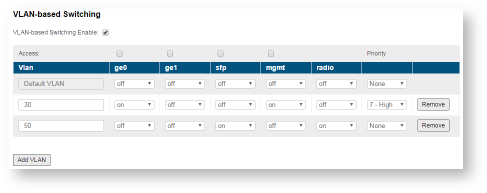 Image Removed Image Removed
|
|
...
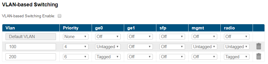 Image Added Image Added
|
|
| Center |
|---|
| Scroll Title |
|---|
| | Mode | Description |
|---|
| off | - Denies all traffic of a specific VLAN
| | Tagged | - Operates as trunk port, allows tagged traffic of a specific VLAN to pass through this port
| | Untagged | - Operates as trunk port, allows untagged traffic of a specific VLAN to pass through this port
| | Access | - Operates as access port, allows only untagged traffic
| | Priority | - Allows to set the priority of a specific VLAN according to 802.1p ranging from 0 to 7, where 0 - the lowest priority level, 7 - the highest.
- There are four priority queues. The mapping between 802.1p priorities and 4 queues can be found below
| Center |
|---|
| 802.1p priority | Traffic type | Unit priority queue |
|---|
| 0 | Background | 1 | | 1 | Best Effort | | 2 | Excellent Effort | 2 | | 3 | Critical Applications | | 4 | Video | 3 | | 5 | Voice | | 6 | Internetwork control | 4 | | 7 | Network control |
|
|
|
|
| Note |
|---|
|
The "Default VLAN" is configured by default as «Untagged» for all ports of the switch:
- In case the "VLAN-based Switching" is enabled, only untagged traffic will be transmitted through the unit ports in such configuration.
- In case the "VLAN-based Switching" is disabled, tagged and untagged traffic will be transmitted through the unit ports. In this case, the connectivity matrix between external interfaces and mgmt interface are enabled, device will be available through any of assigned IP addressess.
"Default VLAN" could not be deleted. |
| Note |
|---|
|
VLANs could be created with ID from 2 to 4094. It is possible to set the ranges of VIDs not just individual tags when configuring VLANs. |
For more detail information about VLAN configuration please refer to the section "VLAN Switching".