The switch page allows you to configure the ports of the unit and the switching related features.
NOTE
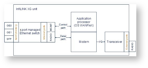
Please make the distinction between the internal "RADIO" port of the Ethernet switch used for the data path separation and the external "RADIO" port of the unit.
The following 5 ports are available at InfiLINK XG:
- "GE0" and "GE1" ports - external copper Gigabit Ethernet ports 1000BASE-T (IEEE 802.1ab)
- "SFP" port - external optical Gigabit port for plugging of the optical SFP transceiver module
- "RADIO" port - internal radio interface of the device
- "MGMT" port - internal interface for the device management.
The switch page has four sections:
- "Switch Port Settings"
- "Port Interconnection Schema"
- "Connectivity matrix"
- "VLAN-based Switching"
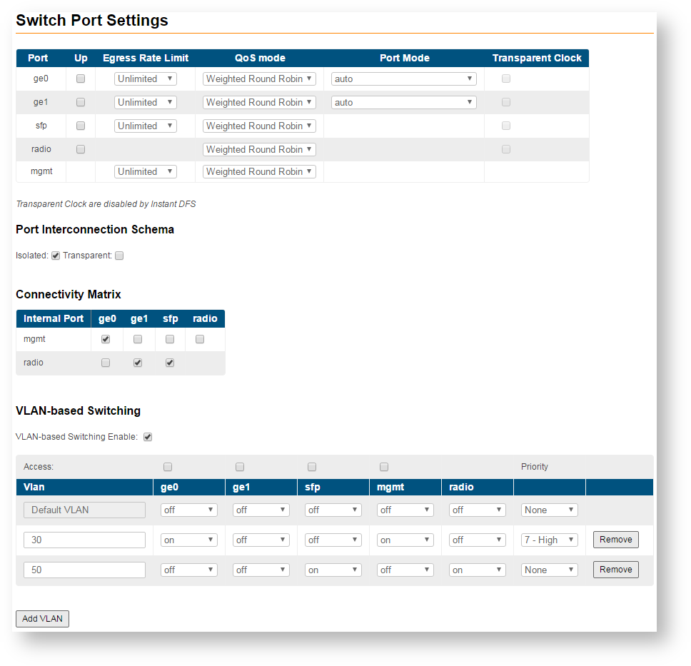
- "Switch Port Settings" - allows you to perform general port configuration
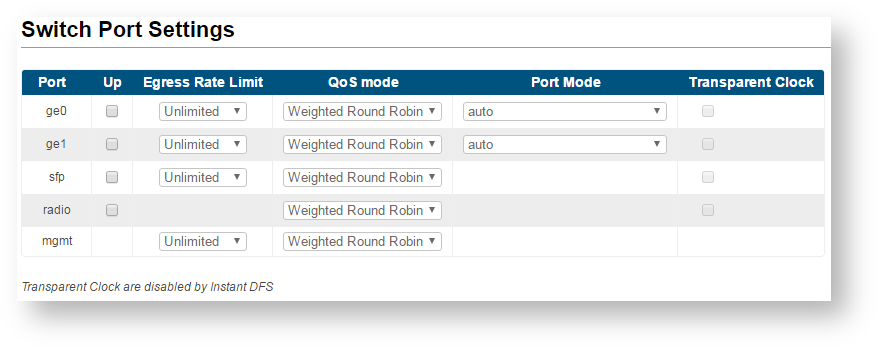
The following port parameters can be customized:
| Parameter | Description |
|---|---|
| Up |
|
| Egress Rate Limit |
|
| QoS mode |
|
| Port Mode |
|
| Transparent Clock |
|
NOTE
Manual settings for the "Port Mode" will disable the negotiation and detection for speed and duplex. Use them in case that the interconnected 3rd party switches have fixed speed and duplex settings.
- "Port Interconnection Schema" allows you to select the switch operation mode:
- "Isolated" - All traffic switching is allowed ONLY between external (ge0, ge1, sfp) and internal ports (mgmt, radio). Thus, direct switching between external ports is forbidden (for example, between "ge0" and "ge1")
- "Transparent" - packet switching is allowed between external and internal ports

- The "Connectivity matrix" allows you to enable or disable switching between internal and external ports of the switch.
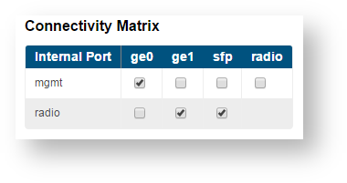
For example, it is quite easy to disable management of the unit via wireless link just by disabling check box between “mgmt” and “radio” ports. Example shown below

- "VLAN-based Switching" allows to create list of allowed VLANs and their handling on InfiLINK XG switch plane. Without such option active, wireless link works as transparent Layer 2 bridge. Thus, the link transport any frames with any VLAN tags set.
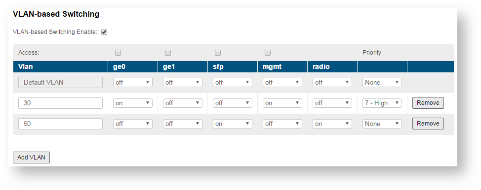
The "Priority" field allows you to set the priority for the selected VLAN according to 802.1p ranging from 0 to 7, where 0 - the lowest priority level, 7 - the highest.