...
- Traffic shaping at the physical interface: limitations will be applied to the whole data flow passing through the physical interface. This method is easy to configure - specify the interface and the threshold value , - but it does not allow to apply limitations to a specific network service traffic.
- Traffic flow shaping: limitations are applied to the logical data flows. The logical data stream is separated from the main traffic by a specified criteria. It allows to apply throughput limitations per network services, which are separated by the values of the service header fields. For example, the traffic tagged with vlan 42 can be separated to a logical channel and limited in throughput without influencing the other traffic flows.
...
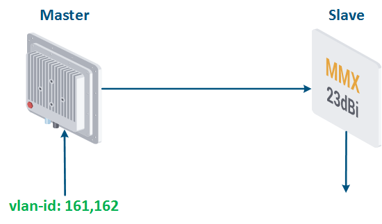
Let's look at the example of transmitting the traffic of two services associated with vlan id's 161 and 162, between Master and Slave (Figure 17a). The total traffic of the services should not exceed 9 Mbps.
...
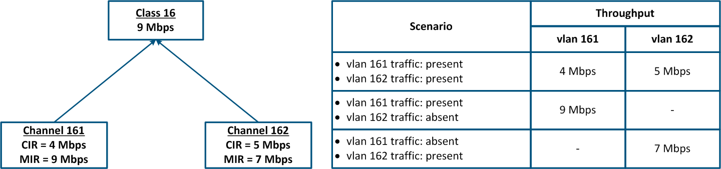
- Class 16 has been configured with a 9 Mbps throughput.
- Class 16 is the parent of the channels 161 and 162, i.e. the total traffic at these logical channels is limited to 9 Mbps.
- The traffic with vlan ID 16 is associated with the logical channel 161; the traffic of vlan 162 is associated with the logical channel 162.
- The CIR value for channel 161 is 4 Mbps and for channel 162 it is 5 Mbps. If both services will actively exchange data, the threshold values for their traffic will be equal to the CIR of each channel.
- The MIR value for channel 161 is 9 Mbps and for channel 162 it is 7 Mbps. If there is no traffic in the logical channel 162, then the threshold value for channel 161 will be equal to the MIR, i.e. 9 Mbps. In the other case, when there is no traffic in the logical channel 161, the threshold value for channel 162 will be equal to 7 Mbps.
| Center |
|---|
Figure 17a - Throughput limitation for 2 traffic flows tagged with vlan-id's ids 161 and 162
Figure 17b - Hierarchical channel structure of the throughput limits for the traffic of vlan's vlans 161 and 162 |
The throughput limitation capabilities of all Infinet families of devices are shown in the table below:
| Center | ||||||||||||||||||||||||||||||||
|---|---|---|---|---|---|---|---|---|---|---|---|---|---|---|---|---|---|---|---|---|---|---|---|---|---|---|---|---|---|---|---|---|
Throughput limitation capabilities in Infinet devices
|
...
- The traffic of all network services should be limited. It allows to take control over all traffic flows and separately allocate resources for these flows.
- The throughput limitation should be performed on the devices closest to the data source. There is no need to duplicate throughput limiting rules for the data flows throughout the chain of intermediate devices.
- Many network services are bidirectional, so they require restrictions on devices for both the incoming and the outgoing traffic.
- To set the correct throughput threshold values, evaluate first the average and the maximum values of the service traffic. Pay special attention to the most busy hours. Collecting data for analysis is possible via the InfiMONITOR monitoring system.
- The sum of the CIR values of the logical channels associated with one class should not exceed the maximum class throughput.
...