| Include Page | ||||
|---|---|---|---|---|
|
| Hide_comments |
|---|
Table of contents
| Table of Contents | ||
|---|---|---|
|
...
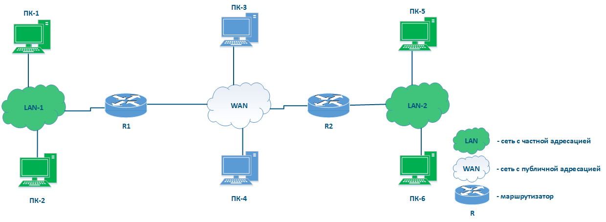
The main task of switching is to ensure the connectivity of the nodes connectivity within one a single network (see. see InfiLINK 2x2 and InfiMAN 2x2: Switching). To organize In order to establish the communication between different networks, different a new class of devices (called routers) must be used (see Figure 1). This article describes the applications application areas and the configuration of the Infinet devices when used as routers.
Terminology
- Switching - the process of connecting endpoint subscribers through intermediate devices. In most modern networks, frame switching is done performed using the Ethernet header, based on the Ethernet header ( destination MAC address and on the vlan ID). In the example from (Figure 1a), the data exchange between PC-1 and PC-2 is performed based on the MAC addresses. In this article, the terms switching and L2 data transmission technology are identical.
- Switch - the device that performs switching.
- Routing - the process of determining the best data transmission path between nodes in belonging to different networks, which is the best according to some a certain criteria. Most modern networks route packets based on the IP header (destination IP address). In the example from (Figure 1b) the data exchange between PC-1 and PC-2 is performed based on the IP addresses. n In this article, the terms routing and L3 data transmission technology are identical.
- Router - the device that performs routing.
- Local network - the network part that is in the responsibility area of the an organization or enterprise. The organization's employees are responsible for assigning IP addresses to the devices on in this network , and an IP address conflict is very unlikely.
- Global network - network having the global scale network. Usually, the Internet is understood as a global network. Since many local networks are connected to the global network, the allocation of the IP addresses allocation is performed centrally, by special organizations.
| Anchor | ||||
|---|---|---|---|---|
|
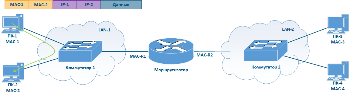
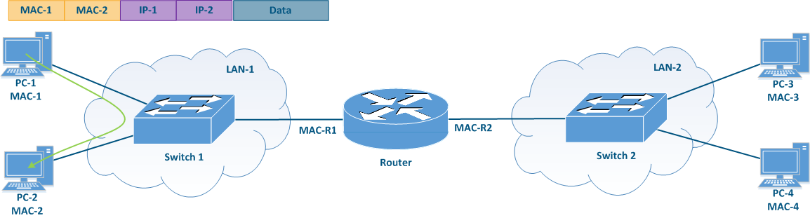
Let's look at the difference differences in the processing of the service headers for data transmission by switching and routing using an example when performing switching compared to routing. The example in (Figure 1) will be used for this purpose.
In the scenario when When PC-1 sends data to PC-2 (Figure 1a), PC-1 fills in the service fields in the following way:
- Destination MAC address: the MAC address of PC-2 - MAC-2;
- Source MAC address: the MAC address of PC-1 - MAC-1;
- Destination IP address: the IP address of PC-2 - IP-2;
- Source IP address: the IP address of PC-1 - IP-1.
The switch receives a the frame from PC-1 and redirects it to PC-2 in accordance with according to the switching table. Thus, The data transmission is performed based on the Ethernet service header, since the transmission is takes place at the data link level. This mechanism is called switching.
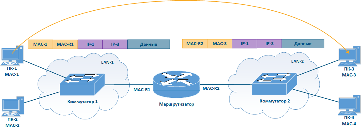
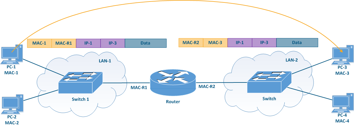
In the scenario when where PC-1 sends data to PC-3 (Figure 1b), PC-1 fills in the frame service fields frame's service fields in the following way:
- Destination MAC address: the router's MAC address - MAC-R2R1;
- Source MAC address: the MAC address of PC-1 - MAC-1;
- Destination IP address: the IP address of PC-3 - IP-3;
- Source IP address: the IP address of PC-1 - IP-1.
The switch receives such a frame and transmits it to the router in accordance with according to the switching table. The router receives the frame, decapsulates the IP packet and transmits it to LAN-2. In this case, the service headers will be set in the following way:
- Destination MAC address: the MAC address of PC-3 - MAC-3;
- Source MAC address: the outer MAC address address of the router - MAC-R2;
- Destination IP address: the IP address of PC-3 - IP-3;
- Source IP address: the IP address of PC-1 - IP-1.
Note that the IP packet header is left unchanged, while the receiver and the sender MAC addresses in the Ethernet frame header are changed. This operation was performed because the MAC addresses are used to transfer data within the same local network, i.e. when transferring data between different local networks, the MAC addresses will always be replaced. This data transfer mechanism is called routing.
| Center |
|---|
Figure 1a - Example of data transmission from PC-1 to PC-2
Figure 1b - Example of data transmission from PC-1 to PC-3 |
Routing
The main networks function of a network is the ability to organize establish the communication between any arbitrary nodes connected to this that are part of the network. Using for these tasks the only packet switching technologies associated with the link Layer 2 (Link layer) of the network interaction model has a number of disadvantages:
- There is a risk of loops appearance Loops can occur when using some data-link protocols such as Ethernet. The risk can be minimized by using third party tools such as STP, but the risk is not limited mitigated by standard Ethernet facilitiesfunctionalities.
- The amount of broadcast traffic amount depends on the number of devices that are connected to the network. To In order to ensure that the amount of broadcast traffic in compared to the total traffic is not large, the number of devices number connected to one broadcast domain should be limited. Thus, all network devices cannot be connected to the same broadcast domain, which makes it impossible using to use L2 layer protocols to organize for establishing global device connectivity.
- Switches to transmit data operate on The switches operate with Ethernet frames , the whose headers of which contain the source and destination devices MAC addresses. Each entry in the switching table contains the MAC address of the device's interface and does not support the mechanism for grouping there is no support for a mechanism that can group these addresses. Thus, ensuring global connectivity will using only L2 switching would require switching tables , which that include the MAC addresses of all the devices in the world at each network node.
The IP network layer protocol, which is widely used to provide connectivity in large and global networks, lacks these disadvantages. IP The IP protocol is not a replacement for Ethernet, these protocols work together and perform different functions: Ethernet provides data transfer within the communication channel, IP devices in the same subnet, while the IP protocol is responsible for global addressing and node communication.the communication between the nodes belonging to different subnets.
Currently, two versions of the IP protocol have become widespread: IPv4 and IPv6. Since Infinet the InfiNet devices currently support only the IPv4 protocol, further the current article will contain only detail the description of only this versionoperation of the IPv4 protocol.
The IP protocol
IP
...
addresses
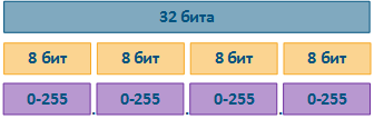
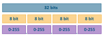
The IP protocol provides for using 32 bits for addressing the nodes in the network, which are usually divided into four octets and written in decimal form, separating the octets with dots (Fig. Figure 2). Examples of IP addresses examples:
- 10.94.200.7
- 192.17.0.0
- 201.15.2.255
| Center |
|---|
Figure 2 - Structure of the IP address structure |
Network mask
The IP provides the grouping of addresses on protocol allows to group the addresses in a network using network masks. A netmask is applied to an IP address, dividing it in two parts: a network ID and a host ID. Devices The devices connected to the same network will have the same network ID and different host IDs. To ensure that the network ID is matching matches on all the devices of a subnet, use the same network mask values when configuring the devices. Host The set of host IDs set allows inferring the number of devices that can be connected to this network and their specifies the IP addresses that can be used by the devices.
The network mask has 32 bits and is written in the same way as the IP address with one difference: the network mask consists of a one bits sequence sequence of ("1") bits followed by zero ("0") bits, i.e. the set of masks is preset and contains 33 values: from 0 to 32. The finite range of possible values allows to write the network mask in an abbreviated form, in which the number of single "1" bits in the mask is indicated after a slash (see the table below).
One The "1" bits in the network mask define the network identifier: the bits of the IP address corresponding to one the "1" bit values of the mask must be fixed and cannot be changed. The remaining bits of the IP address, corresponding to the zero bit values of the mask, can take arbitrary values and determine the host ID.
When configuring the devices connected to the network, the IP addresses are not used without the a network mask, since the routing rules imply a different approach when transferring data to a device from "own" network and to other devices located in a different network, compared to sending data to a device in the same network (see Switching). Note that the network mask is indicated set in the configuration of the device configuration and it is not transmitted in the service header of the IP packet.
| Center | |||||||||||||||||||||||||||||||||||||||
|---|---|---|---|---|---|---|---|---|---|---|---|---|---|---|---|---|---|---|---|---|---|---|---|---|---|---|---|---|---|---|---|---|---|---|---|---|---|---|---|
Table 1 - Network mask examples |
...
Examples of network masks |
Types of IP addresses
The IP address types can be divided according to several criteria:
- by based on its area of application area;
- by belongingbased on its function or role.
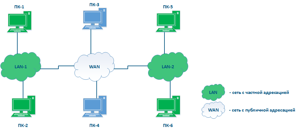
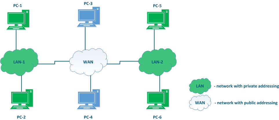
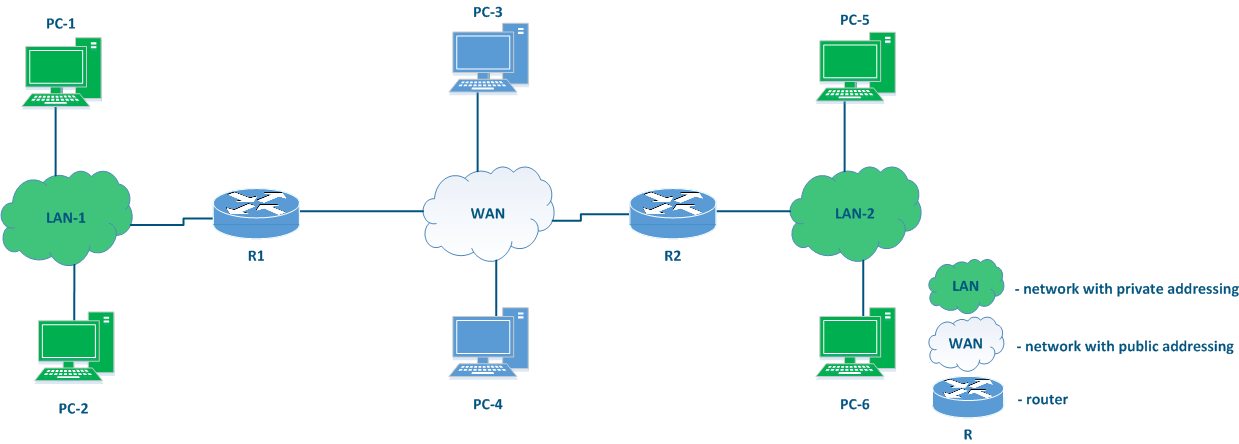
By Based on the application area, the IP addresses can be divided in two large groups: public and private private addresses (Figure 3). Global connectivity can only be established between public addresses, i.e. private addressing is used on inside the enterprise's local network , and public addressing is used on the Internet. The public address is unique, while private addresses can be reused, i.e. the devices PC-2 and PC-6 may have the same address and this is not a problem, since there is no connectivity between LAN-1 and LAN-2. However, the addressing within the same local network must be unique, i.e. the addresses of PC-5 and PC-6 must be different.
In addition to the public and private ranges of addresses, several service ranges are allocated, for example , to transmit for the multicast traffic transmission, for the loopback interface traffic, etc.
| Center |
|---|
Figure 3 - An example of various types networks connecting |
...
network connections |
Based on the function or role, the following addresses can be distinguished:
- Network addressaddresses: the address assigned to this network. Often the network addresses a network, out of which the available host addresses can be deduced. Often the network addresses are used in device the routing tables of the device, as it is shown below. The lowest address from the allowed range is used as the network address: in example 1 - 10.94.200.0 , is the network address and in example 2 - 192.17.0.0 is the network address.
- Broadcast address: recipients of this address are all this address refers to all the devices connected to the network. A packet with a network broadcast address set as the destination will be delivered to all the devices connected to this network. The highest address from the allowed range is used as the broadcast address: in example 1 - 10.94.200.255 , is the broadcast address and in example 2 - 192.17.0.3 is the broadcast address.
- Nodes Node or host addresses: addresses that can be assigned to the network interfaces of the devices connected to the network. All allowed addresses can be used as node addresses, except for the network address and the broadcast address: in example 1 - 10.94.200.1 -till 10.94.200.254 , are node or host addresses and in example 2 - 192.17.0.1-192.17.0.2 are the available node addresses.
...
The place of the router in the network
Figure 3 does not have the elements to connect There is no element explicitly included in Figure 3 that can be used to connect different networks to each other and to transfer data between the networks using IP addressing. Such elements are called routers (Figure 4). Usually, a router connects several networks of an arbitrary type, not just public and private, as shown in the example.
The routers have the following key features:
- The main function of a router is to transfer data between the its connected networks.
- The router is connected to the network by connecting one of the router's interfaces to the network and assigning an IP address from the allowed range to this interface. Both physical and virtual interfaces can be used.
- When transmitting data, the router is guided by by the routing table.
- Data within Within the same network are , data is transmitted using the switching technology, and between different networks - using routing, i.e. IP and Ethernet are complement each other, as mentioned before.
- For the user data, the router is an intermediate device and does not change the source and destination addresses. The source device of the packet source sets the source and destination IP addresses and those remain unchanged along the transmission path.
- The router analyzes only the destination address to find a destination and searches for a best match for it in the routing table. The source address in the service header is set and remains unchanged in order to allow the recipient to send a response packet back to the source device (on the way back, the initial source address will become the destination address).
- The routing table is present not only in specialized network devices such as routers, but also at the end nodes. For example, on a PC using the Windows software controlled PC, the routing table can be displayed by running the "route print" command at in the command line.
| Center |
|---|
Figure 4 - Place The place of the router in the network |
...
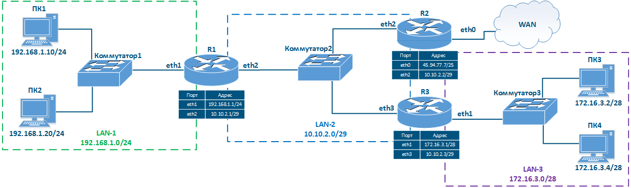
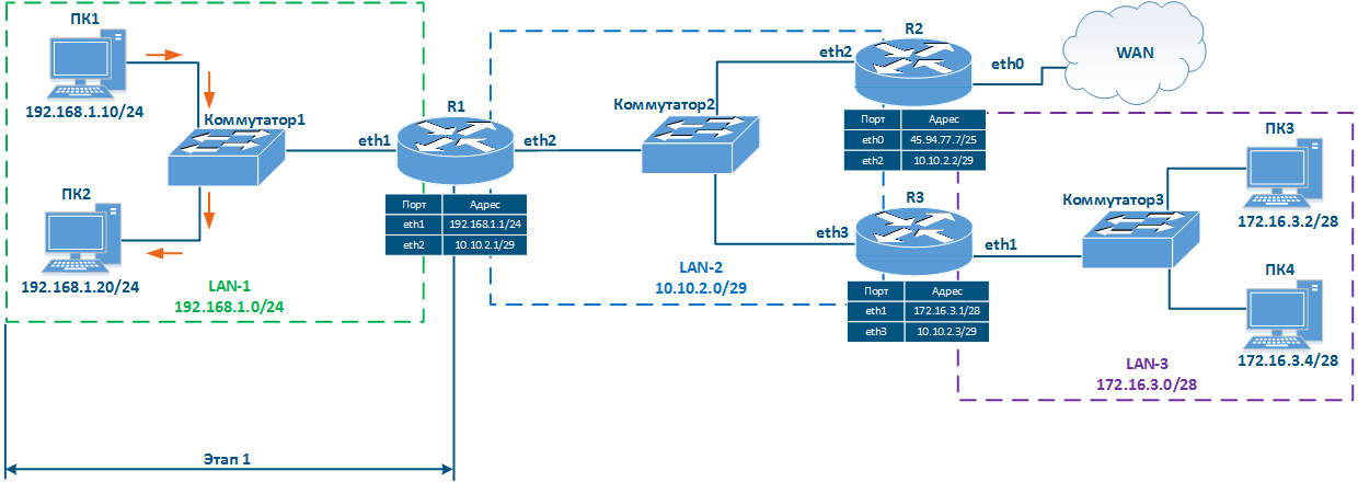
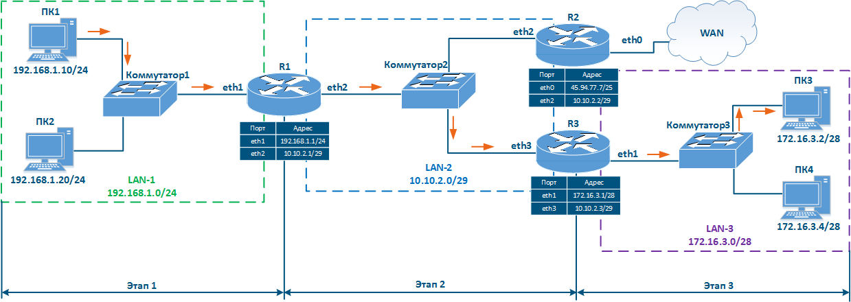
Let's look at the network diagram in (Figure 5), which includes the following elements:
- Local network LAN-1 to connect the network devices PC-1 and PC-2:
- The 192.168.1.0/24 addressing private network address is used in the networkby this segment;
- 192.168.1.10/24 is assigned to PC-1;
- 192.168.1.20/24 is assigned to PC-2;
- 192.168.1.1/24 is assigned to R1.
- Local network LAN-3 to connect the network devices PC-3 and PC-4:
- The 172.16.3.0/28 addressing is used in the networkprivate network address is used by this segment;
- 172.16.3.2/28 is assigned to PC-3;
- 172.16.3.4/28 is assigned to PC-4;
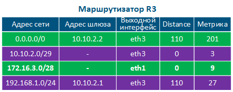
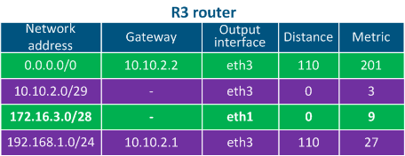
- 172.16.3.1/28 is assigned to R3.
- Local network LAN-2 to connect routers R1, R2 and R3 with to each other:
- The 10.10.2.0/29 addressing is used in the networkprivate network address is used by this segment;
- 10.10.2.1/29 is assigned to R1;
- 10.10.2.2/29 is assigned to R2;
- 10.10.2.3/29 is assigned to R3.
- The connection of the R2 router connection to the WAN global network:
- The 45.94.77.7/25 public host address is assigned to eth0 to the eth0 interface connected to the WAN.
| Center |
|---|
Figure 5 - Network diagram example |

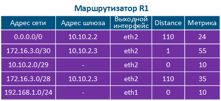
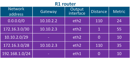
The routing table is an address directory of networks. It contains the location of the networks used for packets transmitting. The routing table may not contain the exact location of a particular network, but there are network interface through which the destination network can be reached. This a collection of network addresses. The network address in the routing table that matches best with the destination IP address has an exit interface or a gateway IP address associated, that are used for transmitting the packet to the corresponding next hop in order to reach the destination. This logic is used by all routers along the traffic path, i.e. if there are 8 routers on along the packet's path, then each of them only has information only about the next router along the way, and this information is contained in the routing table.
...
- Network address: the packet's destination IP address specified in the service header is checked for belonging to see if it belongs to the network whose address is indicated in the table. If the destination belongs to this network, than the current table entry can be used for data transmission. Gateway address: the next router address there The best match is used, which is not always the exact match.
- Gateway address: the IP address of the next router (hop), to which the packet will be forwarded.
- Output interface: the network interface for the outbound packet transmission.
- Distance: in the networks with having redundant communication channels, there are several paths to the same network. These routes can be obtained from one or several sources, however, only one of these routes should be placed in the routing table. To prioritize the routes from different sources, use the Administrative Distance parameter (or Distance) is used, which means reflects the level of trust to into this source. The route from the source with the lowest Distance value will be added to the routing table, as a lower Distance value means a higher level of trust. General The general recommendations for the Distance values are followed by most manufacturers of network equipment (Table 3).
- Metric: a route multiple routes to the same network can be obtained not only from different sources, as mentioned above, but also from the same source. These routes are prioritized using the Metric value, when added to the routing table. Each routes route source calculates the metric using different algorithms, so the metrics from different sources cannot be directly compared.
| Center | |||||||||||||||||||||||||||||||
|---|---|---|---|---|---|---|---|---|---|---|---|---|---|---|---|---|---|---|---|---|---|---|---|---|---|---|---|---|---|---|---|
Table 3 - Distance values depending on the route source |


Routing table management
Each router along the packet transmission path has the a routing table management algorithm. The algorithm is the following:
- Step 1: the destination address is checked for belonging to networks, which entries are against the networks present in the routing table to see if it finds a match.
- Step 2: if few several records satisfy the requirement of step 1, the "narrowest route" is selected, i.e. the entry with having the maximum netmask value is selected. For example, mask /24 is narrower than /8.
- Step 3: if at the step 2 there are several routing table entries with the same network masks, the Distance parameter is compared. The lower the value of this parameter, the higher the priority of the route priority.
- Step 4: if at the step 3 there are several entries in the routing table with the same Distance valuesvalue, the metrics are compared. The lower the metric value, the higher the priority of the route priority.
- Step 5: if there is no entry in the routing table that meets the requirements of step 1 and there is no default route, the packet is dropped.
Routing
...
table management examples
Let's look at the some examples of the routing table management in various scenarios (Figure 6a-c).
...
- Step 1a: PC1 generates a packet with the destination IP address of PC2 and transfers it . The routing table is checked to find a matching network and PC1 determines that PC2 is part of the same directly connected network. The packet is transferred for processing to the L2 layer of the network interface.
- Step 1b: The L2 layer of the PC1's network interface verifies that the destination belongs to the source network. Since PC1 and PC2 belong to the same network, the the PC2 network interface MAC address sends an ARP request to find the MAC address that is associated with the destination IP address, basically the MAC of PC2. The newly discovered MAC address of PC2 is set in the Ethernet header. The generated frame is sent to Switch1.
- Step 1c: The switch transmits the frame to PC2 frame according to the switching table.
Data are is transmitted using switching technologies within the same network using switching technologies, so router R1 does not participate in this process.
| Center |
|---|
Figure 6a - Packet transmission from PC1 to PC2 |

...
Scenario 2 - checking the availability of PC3 from PC1 (source - 192.168.1.10, destination - 172.16.3.2)
- Step 1a: Layer 3 processing: PC1 PC1 generates a packet with the PC3 destination address and sends it for processing to the L2 layer of the network interface.
- Step 1b: The L2 layer of the PC1 network interface verifies that the destination belongs to the source network. PC1 and PC3 belong to different networks, so the R1 router MAC address is set in the Ethernet header as the destination MAC address. The generated frame is sent to Switch1.
- Step 1c: Switch1 transmits frame to R1 in accordance with the switching table.
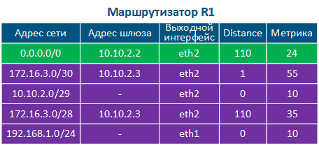
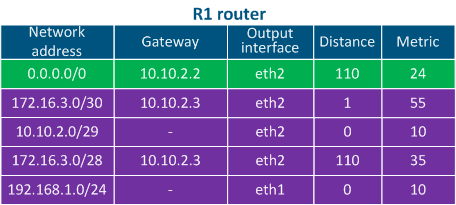
- Step 2a: Router R1 goes through the routing table: two entries match the destination address, IP address of PC3. Also, PC1 checks its routing table to find a matching network for the destination IP address. Here it finds that the best match is network 172.16.3.0/28 which is associated with the gateway (next hop IP address) 192.168.1.1/24 ( the IP address of R1's eth1 interface). Then, the packet is sent for processing to the L2 layer of the network interface.
- Step 1b: The L2 layer of the PC1's network interface sends an ARP request to determine the MAC address corresponding to the gateway IP (the MAC of R1's eth1 interface). The MAC address of the R1's eth1 interface is set in the Ethernet header as the destination MAC address. The generated frame is sent to Switch1.
- Step 1c: Switch1 transmits the frame to R1 according to the switching table.
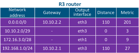
- Step 2a: Router R1 checks its own routing table: two entries match the destination address, 172.16.3.0/28 and 172.16.3.0/30. Since mask /30 is narrower than /28, R1 will redirect the packet to the 172.16.3.0/30 network. Note that if the packet's destination were PC4, a different entry in the routing table would be used, even though PC3 and PC4 belong to the same network.
- Step 2b: Router R1 router forwards the Ethernet frame to towards router R3 router. Source The source and destination IP addresses remain unchanged, as a while the new source MAC address is set the eth2 R1 MAC address, as destination MAC address - the eth3 R3 MAC addressthe one of R1's eth2 interface and the new destination MAC address is the one of the R3's eth3 interface, determined also through the ARP process using the gateway IP address (IP of the R3's eth3 interface).
- Step 2c: The switch forwards the received Ethernet frame Switch 2 receives the frame and forwards it to router R3 according to its switching table.
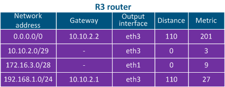
- Step 3a: Router R3 goes through the checks its own routing table: the destination address matches with the 172.16.3.0/28 network which is directly connected to it so it does not need a gateway IP.
- Step 3b: Router R3 sends an determines through ARP the MAC address of PC3 (the destination of the packet) and sends the Ethernet frame to Switch3. The source and destination IP addresses remain unchanged, as a while the source MAC address is set the eth1 R3 interface MAC address, as the one of the R3's eth1 interface and the destination MAC address - is the PC3 network interface MAC address of PC3.
| Center | |||||||||||||||||
|---|---|---|---|---|---|---|---|---|---|---|---|---|---|---|---|---|---|
Figure 6b - Packet transmission from PC1 to PC3
|


Scenario 3 - connection with the "infinetwireless.com" server from PC1 (source - 192.168.1.10, destination - 82.151.200.119)
- Step 1: PC1 generates a packet with the destination IP address 82.151.200.119 (the IP address of the server where the infinetwireless.com website is available). The packet is sent to router R1.
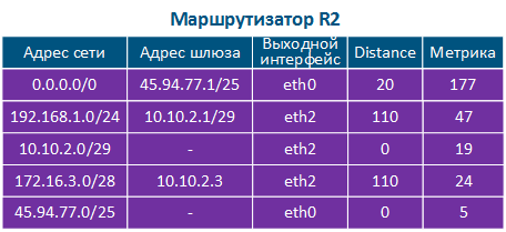
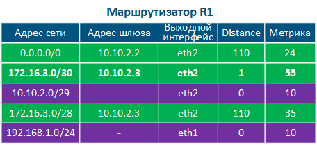
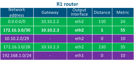
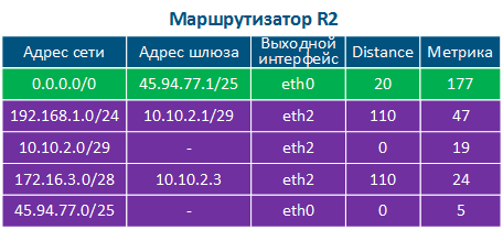
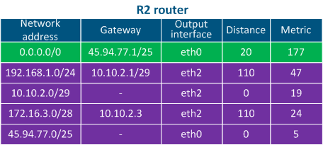
- Step 2: R1 router goes through the checks its routing table: there are no networks in the routing table that match with the destination IP address, so the default route should be usedroute 0.0.0.0/0 having the gateway 10.10.2.2 will be used (see the below routing table of R1). The router sends the packet to R2, its eth2 interface being the gateway.
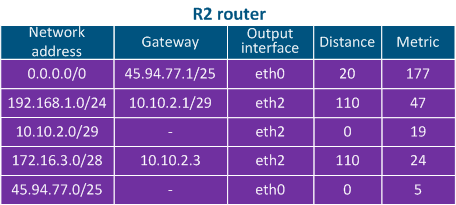
- Step 3: R2 router goes through the checks its routing table: there are no entries matching with the destination IP address, so the default route is used and the packet is sent to a router outside the local network (inside the WAN network).
| Center | |||||||||||||||||
|---|---|---|---|---|---|---|---|---|---|---|---|---|---|---|---|---|---|
Figure 6c - The packet Packet transmission from PC1 to the infinetwireless.com server
|


| Anchor | ||||
|---|---|---|---|---|
|
...
Routing table filling
Speaking about the mechanisms for filling the routing table, two terms should must be added:
- RIB (routing information base) - represents the routing information data obtained from all sources.
- FIB (forwarding information base) - the data forwarding table used to handle transit the transiting traffic. The FIB is generated from the RIB by filtering and combining the routing information (Figure 7).
The sources routing information sources are:
- Operating system routes: service networks used by the device's operating system. For example, the loopback interface network 127.0.0.0/8.
- Directly connected networks: networks to which the device is connected directly, i.e. device the interfaces of the devices are associated assigned with IP addresses that belong to these networks. A Distance parameter of such routes is minimal and equals to 0 The Distance parameter of the directly connected networks has the lowest available value, being equal to 0 - most trusted (Table 2a-c).
- Static routes: routes that are added to the routing table manually. The Distance in case of such the static routes is equal to 1 (Table 2a).
- Dynamic routing protocols: routes obtained using dynamic routing protocols. A Distance value is assigned to each dynamic routing protocol , and some examples are shown in Table 3.
| Center |
|---|
|
| Center |
| Источник маршрутной информации Рисунок Figure 7 - Источники маршрутной информации |
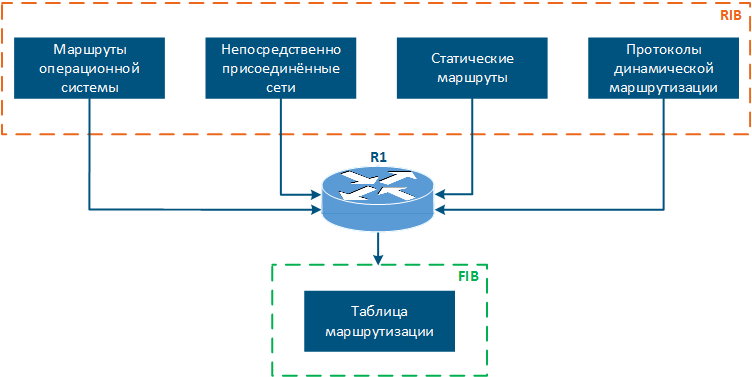
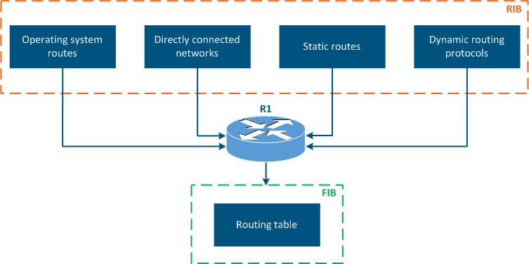
Таблица маршрутизации в устройствах Инфинет
В зависимости от семейства, устройства Инфинет поддерживают различные источники маршрутной информации:
Routing information sources |
The routing table of the Infinet Wireless devices
Depending on the product family, the Infinet Wireless devices support different sources of routing information:
| Center | |||||||||||||||||||||||||||||||||||||||||||||||||||||||||||||||||||||||||||||||||||||||||||||||||||||
|---|---|---|---|---|---|---|---|---|---|---|---|---|---|---|---|---|---|---|---|---|---|---|---|---|---|---|---|---|---|---|---|---|---|---|---|---|---|---|---|---|---|---|---|---|---|---|---|---|---|---|---|---|---|---|---|---|---|---|---|---|---|---|---|---|---|---|---|---|---|---|---|---|---|---|---|---|---|---|---|---|---|---|---|---|---|---|---|---|---|---|---|---|---|---|---|---|---|---|---|---|---|
Таблица 6 - Сравнительная характеристика источников маршрутной информации для устройств Инфинет | |||||||||||||||||||||||||||||||||||||||||||||||||||||||||||||||||||||||||||||||||||||||||||||||||||||
Отображение таблицы маршрутизации
Далее, по ходу статьи, мы будем использовать инструменты вывода и анализа маршрутной информации. Эти инструменты зависят от семейства устройств и будут представлены ниже.
Таблица маршрутизации устройств семейств InfiLINK 2x2, InfiMAN 2x2
Устройства семейств InfiLINK 2x2, InfiMAN 2x2 поддерживают настройку маршрутизации как для трафика управления, так и для пользовательского трафика, причём поддерживаются статические маршруты и протоколы динамической маршрутизации.
Вывод маршрутной информации осуществляется двумя способами:
...
Table 6 - Comparative analysis of the routing information sources for the Infinet devices |
Routing table output
Further in this article we will present the tools for displaying and analyzing the routing information. These tools depend on the family of devices and will be shown below.
The routing tables of the InfiLINK 2x2, InfiMAN 2x2, InfiLINK Evolution, InfiMAN Evolution families of devices
The InfiLINK 2x2, InfiMAN 2x2, InfiLINK Evolution, InfiMAN Evolution families of devices support routing settings for the management traffic and for the user traffic, moreover, static routes and dynamic routing protocols are supported.
The routing information can be displayed in two ways:
- Web interface: go to the "Network settings → Routing parameters" (Figure 8a). The web interface allows to view only the static routes.
- Command line: the "nestat -r" command displays the FIB data. There are also commands available to evaluate the routing information for each type of sources, which will be described in the following sections.
| Center | |||||||
|---|---|---|---|---|---|---|---|
Рисунок 8а - Пример просмотра маршрутной информации на устройствах семейств InfiLINK 2x2, InfiMAN 2x2 |
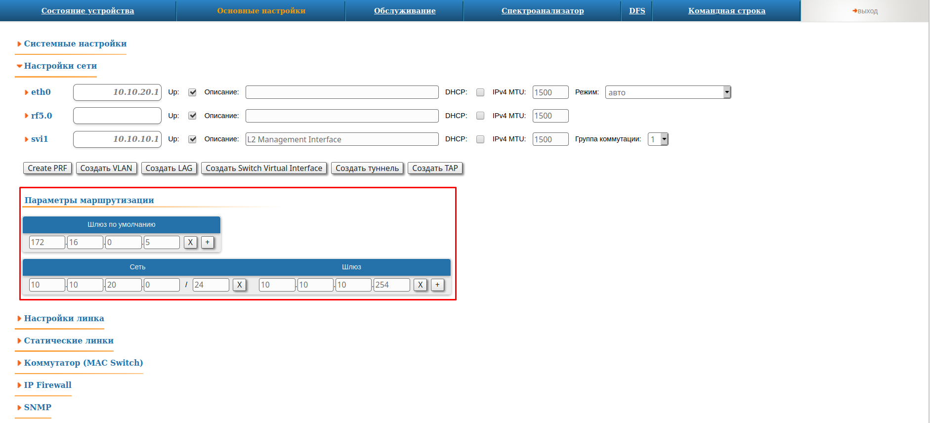
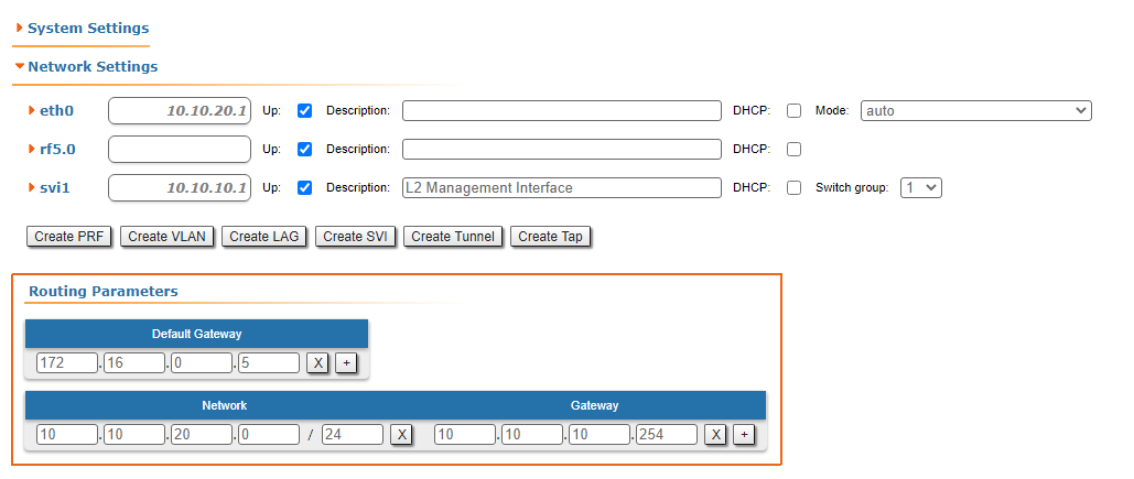
Таблица маршрутизации устройств семейств InfiLINK XG, InfiLINK XG 1000
Устройства семейств InfiLINK XG, InfiLINK XG 1000 поддерживают только настройку маршрутизации для трафика управления. Можно указать шлюз по умолчанию и добавить статические маршруты. Вывод таблицы маршрутизации осуществляется двумя способами:
...
Figure 8a - An example of routing information output for the InfiLINK 2x2, InfiMAN 2x2, InfiLINK Evolution, InfiMAN Evolution families of devices |
The routing tables of the InfiLINK XG and InfiLINK XG 1000 families of devices
The InfiLINK XG and InfiLINK XG 1000 families of devices support routing configurations for the management traffic only. The default gateway and static routes can be set. The routing information can be displayed in two ways:
- Web interface: go to the "Network access" section (Figure 8b).
- Command line: run the "nestat -r" command.
| Center | |||||||
|---|---|---|---|---|---|---|---|
Рисунок 8б - Пример просмотра маршрутной информации на устройствах семейств InfiLINK XG, Figure 8b -An example of routing information output for the InfiLINK XG/InfiLINK XG 1000 |
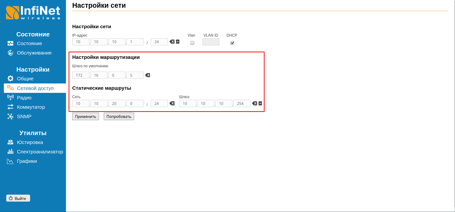
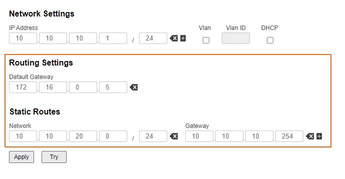
Таблица маршрутизации устройств семейств Vector 5, Vector 70
Устройства семейств Vector 5, Vector 70 поддерживают только настройку маршрутизации для трафика управления, позволяя указать шлюз по умолчанию. Вывод таблицы маршрутизации осуществляется двумя способами:
...
families of devices |
The routing tables of the Quanta 5, Quanta 6 and Quanta 70 families of devices
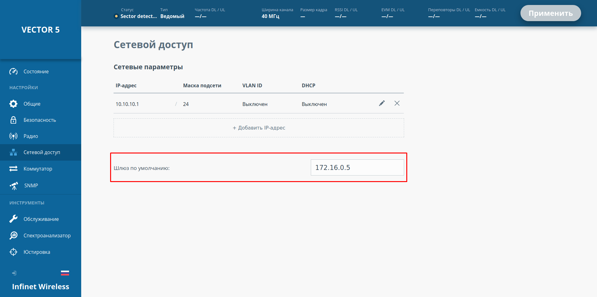
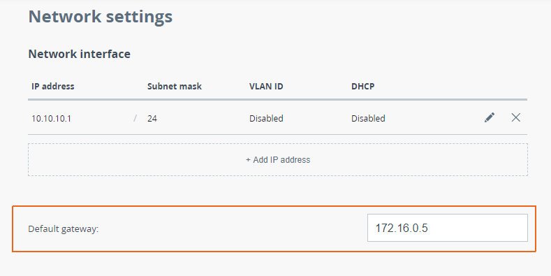
The Quanta 5, Quanta 6 and Quanta 70 families of devices support only routing configurations for the management traffic, allowing to set a default gateway. The routing information can be displayed in two ways:
- Web interface: go to the "Network" section (Figure 8c).
- Command line: run the "nestat -r" command.
| Center | |||||||
|---|---|---|---|---|---|---|---|
Рисунок 8в - Пример просмотра маршрутной информации на устройствах семейства Vector 5, Vector 70Figure 8c - An example of routing information output for the Quanta 5, Quanta 6, Quanta 70 families of devices |
| Tip | ||
|---|---|---|
| ||
Продолжение статьи доступно по ссылке: Статическая маршрутизация. |
Дополнительные материалы
Онлайн-курсы
- Предварительная настройка и установка устройств семейств InfiLINK 2x2 и InfiMAN 2x2
- Коммутация в устройствах семейств InfiLINK 2x2 и InfiMAN 2x2.
- Устройства семейства InfiLINK XG
- Vector 5: установка и настройка
Вебинары
- Типовые сценарии настройки маршрутизации в устройствах Инфинет. Часть 1.
- Типовые сценарии настройки маршрутизации в устройствах Инфинет, часть 2.
Прочее
...
| |
The article continues with: Static routing |
Additional materials
Online courses
- InfiLINK 2x2 / InfiMAN 2x2: Initial Link Configuration and Installation
- InfiLINK 2x2 and InfiMAN 2x2: Switching
- InfiLINK XG Family Product
- Quanta 5 / Quanta 6: Installation and Configuration
Webinars
- Typical scenario of routing setting using Infinet Wireless devices. Part I.
- Typical scenario of routing setting using Infinet Wireless devices. Part II