Table of
...
contents
| Table of Contents |
|---|
| exclude | Список документов|Содержание |
|---|
|
Description
The OSPF configuration is performed only via CLI. A separate command shell with several modes is used to configure the OSPF protocol (Figure 1). The transition to each mode is performed using the commands with having the same name as the mode. A detailed description of the commands description is available in Technical documentationin the Technical documentation.
| Note |
|---|
|
An configuration example is given for the InfiLINK 2x2, InfiMAN 2x2 families devices, pay attention to the name of the radio interface on your devices during the scheme implementation. |
| Mode name | Description |
|---|
| Basic | Basic The basic OSPF mode is used to analyze the output of the diagnostic commands output and to switch to the configuration mode. Switching to the basic mode is performed from the WANFleX command shell using the "ospf" command. | Code Block |
|---|
| BS_1#1> ospf
OSPF> |
|
| OSPF configuration | Configuration The configuration mode allows to manage the OSPF service running on the device and to proceed to the additional configuration modes, : router, interfaces , or route-maps. Switching The switching to the OSPF configuration mode is performed from the basic mode using the "config" command. | Code Block |
|---|
| OSPF> config
OSPF(config)# |
|
| OSPF router configuration | In the router configuration mode, the basic OSPF settings are made. The can be performed. This mode allows to configure the announced networks, the areas, the router ID, etc. Switching The switching to the OSPF router configuration mode is performed from the configuration mode using the "router" command. | Code Block |
|---|
| OSPF(config)# router
OSPF(config-router)#
|
|
| OSPF interface configuration | The OSPF interface configuration mode allows to configure the protocol settings related to a specific interface. Switching The switching to the OSPF interface configuration mode is performed from the configuration mode using the "interface IFNAME" command. | Code Block |
|---|
| OSPF(config)# interface rf5.0
OSPF(config-if)# |
|
| Route-maps configuration | RouteThe route-maps configuration mode allows to configure the rules that should be applied to the announced or received OSPF routes. Switching The switching to the OSPF route-map configuration mode is performed from the configuration mode using the rule creation command "route-map WORD (deny|permit) <1-65535>". | Code Block |
|---|
| OSPF(config)# route-map MAP permit 10
OSPF(config-route-map)# |
|
| Center |
|---|
| Gliffy Diagram |
|---|
| displayName | ospf_shell |
|---|
| name | ospf_shell |
|---|
| pagePin | 1 |
|---|
|
Figure 1 - Scheme of switching Switching between the OSPF command shell modes |
Each OSPF shell modes mode provides help by displaying the full list of supported commands. To display the list use the "help" command.
The routing table can be displayed by using one of the following commands:
| Code Block |
|---|
|
From WANFleX command shell:
BS_1#1> netstat -r

From OSPF command shell:
OSPF> show route

From ARDA command shell:
ARDA> show route |
...
Network scheme with one OSPF area
To In order to demonstrate how to configure the OSPF protocol and analyze the output of the diagnostic commands output, let's take a look at the example of the scheme with one OSPF area in (Figure 2):
- The network consists of three wireless devices BS1, CPE2 , and CPE3 configured as routers.
- Wireless devices build The wireless devices are part of the OSPF backbone area 0 (only one OSPF area is present in this setup).
- BS1 has an external link for connecting to the LAN-1 network.
- The CPE3 router is connected to the outside external router R1.To make the R1's router networks available, static routes to the networks 192.168.5.0/28 and 192.168.6.0/28 have been added to CPE3.
- Routers BS1, CPE2 and CPE3 use as identifiers the addresses assigned to the loopback interface: 192.168.0.1/32, 192.168.0.2/32 and 192.168.0.3/32.
| Center |
|---|
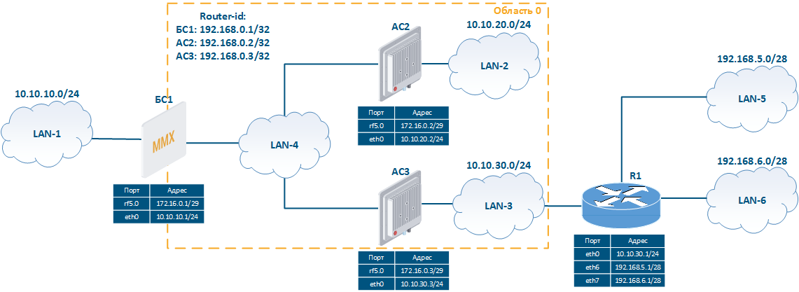 Image Removed Image Removed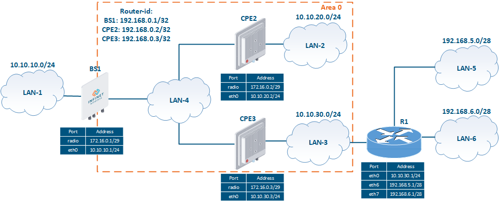 Image Added Image Added
Figure 2 - Network scheme with one OSPF area |
Pre-configuration
| Description | Perform a devices preliminary configuration of the wireless devices, consisting of the following steps: - Configure the device IDIDs.
- Remove the svi1 interface.
- Assign IP addresses to network interfaces, according to the scheme.
- Add static entries to the routing table.
- Disable switching.
- Set Establish the wireless links.
|
|---|
| BS1 | | Code Block |
|---|
| ConfigureSet the device ID
system prompt BS_1
Remove the svi1 interface
ifc svi1 destroy
Assign IP addresses
ifc eth0 10.10.10.1/24
ifc rf5.0 172.16.0.1/29
ifc lo0 192.168.0.1/32
Disable switching
switch stop
SetEstablish wireless links
rf rf5.0 band 20
rf rf5.0 freq 5000
mint rf5.0 -name "BS_1"
mint rf5.0 -type master |
|
|---|
| CPE2 | | Code Block |
|---|
| ConfigureSet the device ID
system prompt CPE_2
Remove the svi1 interface
ifc svi1 destroy
Assign IP addresses
ifc eth0 10.10.20.2/24
ifc rf5.0 172.16.0.2/29
ifc lo0 192.168.0.2/32
Disable switching
switch stop
SetEstablish athe wireless link
mint rf5.0 -name "CPE_2"
mint rf5.0 -type slave
mint rf5.0 prof 1 -band 20 -freq 5000 -type slave |
|
|---|
| CPE3 | | Code Block |
|---|
| ConfigureSet the device ID
system prompt CPE_3
Remove the svi1 interface
ifc svi1 destroy
Assign IP addresses
ifc eth0 10.10.30.3/24
ifc rf5.0 172.16.0.3/29
ifc lo0 192.168.0.3/32
Add static routes
route add 192.168.5.0/28 10.10.30.1
route add 192.168.6.0/28 10.10.30.1
Disable switching
switch stop
SetEstablish athe wireless link
mint rf5.0 -name "CPE_3"
mint rf5.0 -type slave
mint rf5.0 prof 1 -band 20 -freq 5000 -type slave |
|
|---|
OSPF configuration
| Description | Configure the OSPF protocol in accordance with according to the scheme. Step 1: start OSPF. Step 2: set routers the router IDs. The identifiers will be equal to the IP addresses assigned to the loopback interface. Step 3: define the interfaces where OSPF should be started. All the interfaces are connected to the backbone area according to the scheme. On the BS1 and CPE3 routers, set define the networks assigned to one of the device's interfaces that should take part in OSPF. On the CPE2 router, set all the networks using only one entry 0.0.0.0/0. This entry includes all networks and enables the OSPF support on all router's interfaces; when some a device interfaces 's interface is connected to a new network, this network will be immediately announced via OSPF. This approach doesn't require additional OSPF configuration, but decreases the control over the announcements. In addition, this command announces advertises the address 127.0.0.1/32 that is assigned to the loopback interface and does not announce the address 192.168.0.2/32, therefore, this network must be additionally specified. Step 4: make perform the redistribution of the directly connected networks on to the BS1 router and of the static routes on the CPE3 router. Step 5: configure passive interfaces. The CPE3 eth0 interface of CPE3 is connected to the outside external router R1, so no neighbor relationship neighboring relation should be established on this interface. Network 10.10.30.0/24 associated with the eth0 interface must be announced via OSPF, so the eth0 interface must be set as passive. |
|---|
| BS1 | | Code Block |
|---|
| Start OSPF
ospf start
Set the router-id
ospf
config
router
router-id 192.168.0.1
Start OSPF on the interfaces
ospf
config
router
network 172.16.0.0/29 area 0.0.0.0
network 192.168.0.1/32 area 0.0.0.0
ConnectedRedistribution of the connected routes redistribution
ospf
config
router
redistribute connected |
|
|---|
| CPE2 | | Code Block |
|---|
| Start OSPF
ospf start
Set the router-id
ospf
config
router
router-id 192.168.0.2
Start OSPF on the interfaces
ospf
config
router
network 0.0.0.0/0 area 0.0.0.0
network 192.168.0.2/32 area 0.0.0.0 |
|
|---|
| CPE3 | | Code Block |
|---|
| Start OSPF
ospf start
Set the router-id
ospf
config
router
router-id 192.168.0.3
Start OSPF on the interfaces
ospf
config
router
network 10.10.30.0/24 area 0.0.0.0
network 172.16.0.0/29 area 0.0.0.0
network 192.168.0.3/32 area 0.0.0.0
StaticRedistribute the static routes redistribution
ospf
config
router
redistribute kernel
PassiveConfigure the passive interfaces configuration
passive-interface eth0 |
|
|---|
Command output
...
analysis
Neighbors list
| Description | Analyze neighors list outputthe neighbors. The routers are connected by through the 172.16.0.0/29 network, which is a broadcast segment (using the MINT protocol), so: - CPE3 is selected elected as DR, its router-id is being the highest.
- CPE2 is selected elected as BDR, its router-id less than CPE3, but more than BS1being the highest after CPE3.
- BS1 is becomes DROther.
- The routers have established a Full relationshiprelations.
|
|---|
| BS1 | | Code Block |
|---|
| OSPF> show neighbor
Neighbor ID Pri State Dead Time Address Interface RXmtL RqstL DBsmL
192.168.0.2 1 Full/Backup 00:00:38 172.16.0.2 rf5.0:172.16.0.1 0 0 0
192.168.0.3 1 Full/DR 00:00:38 172.16.0.3 rf5.0:172.16.0.1 0 0 0 |
|
|---|
| CPE2 | | Code Block |
|---|
| OSPF> show neighbor
Neighbor ID Pri State Dead Time Address Interface RXmtL RqstL DBsmL
192.168.0.1 1 Full/DROther 00:00:33 172.16.0.1 rf5.0:172.16.0.2 0 0 0
192.168.0.3 1 Full/DR 00:00:35 172.16.0.3 rf5.0:172.16.0.2 0 0 0 |
|
|---|
| CPE3 | | Code Block |
|---|
| OSPF> show neighbor
Neighbor ID Pri State Dead Time Address Interface RXmtL RqstL DBsmL
192.168.0.1 1 Full/DROther 00:00:31 172.16.0.1 rf5.0:172.16.0.3 0 0 0
192.168.0.2 1 Full/Backup 00:00:37 172.16.0.2 rf5.0:172.16.0.3 0 0 0 |
|
|---|
LSDB content
| Description | Analyze the LSDB. Since the scheme contains one area, the LSDB output on all the routers will be identical: - LSA type 1 (Router Link States): the LSDB contains three LSA LSAs type 1, one from each of the area routers. Note , that each LSA can contain a lot of information. For example, the LSA type 1 generated by CPE2 contains information about the neighbors, about the 172.16.0.0/29 , and 10.10.20.0/24 networks and its own identifier.
- LSA type 2 (Net Link States): CPE3 router as DR generates has generated one LSA type 2.
- LSA type 5 (AS External Link States): by default, one LSA type 5 is generated for each external route, therefore the LSDB contains three LSA LSAs type 5 about routes to external networks: , one for each external network: the routes to the networks 192.168.5.0/28 and 192.168.6.0/28 were generated during the redistribution of the CPE3's static routes , and the route to network 10.10.10.0/24 is generated by BS1 during the redistribution of as a directly connected network.
|
|---|
| BS1, CPE2, CPE3 | | Code Block |
|---|
| OSPF> show database
OSPF Router with ID (192.168.0.1)(192.168.0.1)
Router Link States (Area 0.0.0.0)
Link ID ADV Router Age Seq# LS-Age Link count
192.168.0.1 192.168.0.1 202 0x80000008 7442 2
192.168.0.2 192.168.0.2 201 0x80000008 7405 3
192.168.0.3 192.168.0.3 204 0x8000000a 7407 3
Net Link States (Area 0.0.0.0)
Link ID ADV Router Age Seq# LS-Age Routers
172.16.0.3/29 192.168.0.3 204 0x80000006 7407 3
AS External Link States
Link ID ADV Router Age Seq# LS-Age Route
10.10.10.0 192.168.0.1 122 0x80000007 7442 E2 10.10.10.0/24 [0x0]
192.168.5.0 192.168.0.3 169 0x80000007 7407 E2 192.168.5.0/28 [0x0]
192.168.6.0 192.168.0.3 299 0x80000007 7407 E2 192.168.6.0/28 [0x0] |
|
|---|
Routing table
| Description | The routing tables of the wireless devices , contains contain entries that each device has information about each subnet for each subnet shown in the scheme. This means that the devices have successfully exchanged the routing information and added it to the FIB. Note , that the addresses of the loopback interfaces addresses do not depend on the links link state, therefore they can be used to manage the devices in redundant networks. |
|---|
| BS1 | | Code Block |
|---|
| BS_1#1> netstat -r
Routing tables
Destination Gateway Flags Refs Use Interface
10.10.10.0/24 link#2 UC 0 0 eth0
10.10.20.0/24 172.16.0.2 UG3 0 0 rf5.0
10.10.30.0/24 172.16.0.3 UG3 0 0 rf5.0
127.0.0.1 127.0.0.1 UH 3 141 lo0
172.16.0.0/29 link#3 UC 0 0 rf5.0
192.168.0.1 192.168.0.1 UH 0 0 lo0
192.168.0.2 172.16.0.2 UGH3 0 0 rf5.0
192.168.0.3 172.16.0.3 UGH3 0 0 rf5.0
192.168.5.0/28 172.16.0.3 UG3 0 0 rf5.0
192.168.6.0/28 172.16.0.3 UG3 0 0 rf5.0
224.0.0.0/8 127.0.0.1 UGS 1 1561 lo0 |
|
|---|
| CPE2 | | Code Block |
|---|
| AS_2#2> netstat -r
Routing tables
Destination Gateway Flags Refs Use Interface
10.10.10.0/24 172.16.0.1 UG3 0 0 rf5.0
10.10.20.0/24 link#2 UC 0 0 eth0
10.10.30.0/24 172.16.0.3 UG3 0 0 rf5.0
127.0.0.1 127.0.0.1 UH 3 50 lo0
172.16.0.0/29 link#3 UC 0 0 rf5.0
192.168.0.1 172.16.0.1 UGH3 0 0 rf5.0
192.168.0.2 192.168.0.2 UH 0 0 lo0
192.168.0.3 172.16.0.3 UGH3 0 0 rf5.0
192.168.5.0/28 172.16.0.3 UG3 0 0 rf5.0
192.168.6.0/28 172.16.0.3 UG3 0 0 rf5.0
224.0.0.0/8 127.0.0.1 UGS 1 2037 lo0 |
|
|---|
| CPE3 | | Code Block |
|---|
| AS_3#1> netstat -r
Routing tables
Destination Gateway Flags Refs Use Interface
10.10.10.0/24 172.16.0.1 UG3 0 0 rf5.0
10.10.20.0/24 172.16.0.2 UG3 0 0 rf5.0
10.10.30.0/24 link#2 UC 0 0 eth0
127.0.0.1 127.0.0.1 UH 3 155 lo0
172.16.0.0/29 link#3 UC 0 0 rf5.0
192.168.0.1 172.16.0.1 UGH3 0 0 rf5.0
192.168.0.2 172.16.0.2 UGH3 0 0 rf5.0
192.168.0.3 192.168.0.3 UH 0 0 lo0
192.168.5.0/28 10.10.30.1 UGS 0 0 eth0
192.168.6.0/28 10.10.30.1 UGS 0 0 eth0
224.0.0.0/8 127.0.0.1 UGS 1 1745 lo0 |
|
|---|
Схема с несколькими областями
Рассмотрим пример схемы сети с несколькими областями OSPF (рис. 3):
...
Network scheme with several OSPF areas
Let's look at the example of a network scheme using several OSPF areas (Figure 3):
- The network consists of four wireless devices BS1, CPE2, CPE3 and CPE4, configured in the router mode.
- The wireless devices are part of three OSPF areas:
- area 0: routers BS1 and CPE2 are connected to this area. The BS1 router has an external network connection;
- area 3: routers BS1 and CPE3 are connected to this area, the area's type is NSSA. The CPE3 router has an external link with router R1 and two static routes to the networks 192.168.5.0/28 и and 192.168.6.0/28;
- область 4: к области подключены маршрутизаторы БС1 и АС4, тип области Stub.
В качестве идентификаторов маршрутизаторы БС1, АС2, АС3 и АС4 используют адреса, ассоциированные с интерфейсом loopback, - area 4: routers BS1 and CPE4 are connected to this area, the area's type is Stub.
- Routers BS1, CPE2, CPE3 and CPE4 use the addresses assigned to the loopback interface as identifiers: 192.168.0.1/32, 192.168.0.2/32, 192.168.0.3/32 и and 192.168.0.4/32 соответственно.
| Center |
|---|
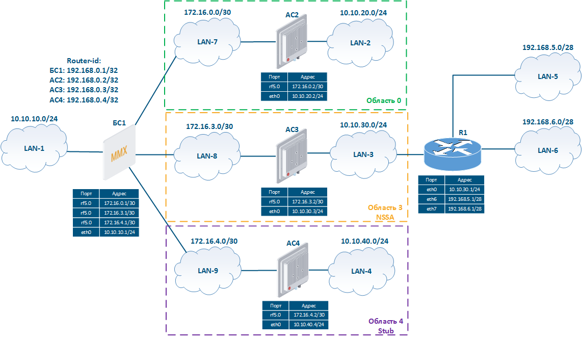 Image Removed Image Removed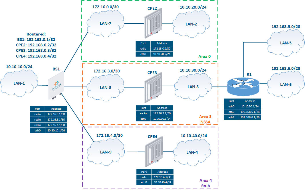 Image Added Image Added
Рисунок Figure 3 - Схема сети с несколькими областями OSPF |
Предварительная настройка
...
Выполним предварительную настройку устройств, состоящую из следующих этапов:
...
Network scheme with several OSPF areas |
Pre-configuration
| Description | Perform a preliminary configuration of the wireless devices consisting of the following steps: - Configure the router IDs.
- Remove the svi1 interface.
- Assign IP addresses to network interfaces, according to the scheme.
- Add static entries to the routing table.
- Disable switching.
- Establish the wireless links.
|
|---|
| BS1 | | Code Block |
|---|
| Установка идентификатораSet the device ID
system prompt BS_1
УдалениеRemove интерфейсаthe svi1 interface
ifc svi1 destroy
НазначениеAssign IP-адресов addresses
ifc eth0 10.10.10.1/24
ifc rf5.0 172.16.0.1/30
ifc rf5.0 172.16.3.1/30
ifc rf5.0 172.16.4.1/30
ifc lo0 192.168.0.1/32
ОтключениеDisable коммутацииswitching
switch stop
Установка радиоканалаEstablish the radio link
rf rf5.0 band 20
rf rf5.0 freq 5000
mint rf5.0 -name "BS_1"
mint rf5.0 -type master |
|
|---|
| CPE2 | | Code Block |
|---|
| Установка идентификатораSet the device ID
system prompt ASCPE_2
УдалениеRemove интерфейсаthe svi1 interface
ifc svi1 destroy
НазначениеAssign IP-адресов addresses
ifc eth0 10.10.20.2/24
ifc rf5.0 172.16.0.2/30
ifc lo0 192.168.0.2/32
ОтключениеDisable коммутацииswitching
switch stop
Установка радиоканалаEstablish the radio link
mint rf5.0 -name "ASCPE_2"
mint rf5.0 -type slave
mint rf5.0 prof 1 -band 20 -freq 5000 -type slave |
|
|---|
| CPE3 | | Code Block |
|---|
| Установка идентификатораSet the device ID
system prompt ASCPE_3
УдалениеRemove интерфейсаthe svi1 interface
ifc svi1 destroy
НазначениеAssign IP-адресов addresses
ifc eth0 10.10.30.3/24
ifc rf5.0 172.16.3.2/30
ifc lo0 192.168.0.3/32
ДобавлениеAdd статическихstatic маршрутовroutes
route add 192.168.5.0/28 10.10.30.1
route add 192.168.6.0/28 10.10.30.1
ОтключениеDisable коммутацииswitching
switch stop
Установка радиоканалаEstablish the radio link
mint rf5.0 -name "ASCPE_3"
mint rf5.0 -type slave
mint rf5.0 prof 1 -band 20 -freq 5000 -type slave |
|
|---|
| CPE4 | | Code Block |
|---|
| Установка идентификатораSet the device ID
system prompt ASCPE_4
УдалениеRemove интерфейсаthe svi1 interface
ifc svi1 destroy
НазначениеAssign IP-адресов addresses
ifc eth0 10.10.40.4/24
ifc rf5.0 172.16.4.2/30
ifc lo0 192.168.0.4/32
ОтключениеDisable коммутацииswitching
switch stop
Установка радиоканалаEstablish the radio link
mint rf5.0 -name "ASCPE_4"
mint rf5.0 -type slave
mint rf5.0 prof 1 -band 20 -freq 5000 -type slave |
|
|---|
...
OSPF configuration
| Description | Выполним настройку протокола OSPF в соответствии со схемой. Этап 1: запустим службу Let's configure the OSPF protocol according to the scheme. Step 1: start OSPF. Этап Step 2: установим идентификаторы маршрутизаторов. Идентификаторы будут идентичны IP-адресам, ассоциированным с интерфейсом loopback. Этап 3: определим интерфейсы, на которых должен быть запущен OSPF. Все интерфейсы подключены к магистральной области, в соответствии со схемой. Этап 4: определим типы областей: область 3 - NSSA, область 4 - Stub. Следует иметь в виду, что тип области должен быть настроен на всех маршрутизаторах, подключенных к этой области, иначе они не установят соседские отношения. Этап 5: выполним редистрибуцию непосредственно присоединённых сетей на маршрутизаторе БС1 и статических маршрутов на маршрутизаторе АС3. Этап 6: определим пассивные интерфейсы configure the router IDs. The identifiers will be equal to the IP addresses assigned to the loopback interface. Step 3: define the interfaces where OSPF should be started. All the interfaces are connected to the backbone area according to the scheme. Step 4: define the area types: area 3 - NSSA, area 4 - Stub. Note that the area type must be configured on all the routers connected to that area, otherwise they will not establish neighboring relations. Step 5: perform the redistribution of the directly connected networks on the BS1 router and of the static routes on the CPE3 router. Step 6: configure passive interfaces. |
|---|
| BS1 | | Code Block |
|---|
| Запуск службыStart OSPF
ospf start
УстановкаSet the router-id
ospf
config
router
router-id 192.168.0.1
ЗапускStart OSPF on наthe интерфейсахinterfaces
ospf
config
router
network 172.16.0.0/30 area 0.0.0.0
network 172.16.3.0/30 area 0.0.0.3
network 172.16.4.0/30 area 0.0.0.4
network 192.168.0.1/32 area 0.0.0.0
ОпределениеSet the типаarea областейtypes
ospf
config
router
area 0.0.0.3 nssa
area 0.0.0.4 stub
РедистрибуцияRedistribute the connected-маршрутов routes
ospf
config
router
redistribute connected |
|
|---|
| CPE2 | | Code Block |
|---|
| Запуск службыStart OSPF
ospf start
УстановкаSet the router-id
ospf
config
router
router-id 192.168.0.2
ЗапускStart OSPF наon the интерфейсахinterfaces
ospf
config
router
network 10.10.20.0/24 area 0.0.0.0
network 172.16.0.0/30 area 0.0.0.0
network 192.168.0.2/32 area 0.0.0.0 |
|
|---|
| CPE3 | | Code Block |
|---|
| Запуск службыStart OSPF
ospf start
УстановкаSet the router-id
ospf
config
router
router-id 192.168.0.3
ЗапускStart OSPF on наthe интерфейсахinterfaces
ospf
config
router
network 10.10.30.0/24 area 0.0.0.3
network 172.16.3.0/30 area 0.0.0.3
network 192.168.0.3/32 area 0.0.0.3
ОпределениеSet the типаarea областейtypes
ospf
config
router
area 0.0.0.3 nssa
РедистрибуцияRedistribute the статическихstatic маршрутовroutes
ospf
config
router
redistribute kernel
ОпределимSet the пассивныеpassive интерфейсыinterfaces
passive-interface eth0 |
|
|---|
| CPE4 | | Code Block |
|---|
| Запуск службыStart OSPF
ospf start
УстановкаSet the router-id
ospf
config
router
router-id 192.168.0.4
ЗапускStart OSPF on наthe интерфейсахinterfaces
ospf
config
router
network 10.10.40.0/24 area 0.0.0.4
network 172.16.4.0/30 area 0.0.0.4
network 192.168.0.4/32 area 0.0.0.4
Определение типа областей
Set the area types
ospf
config
router
area 0.0.0.4 stub
РедистрибуцияRedistribute the статическихstatic маршрутовroutes
ospf
config
router
redistribute kernel |
|
|---|
Анализ вывода команд
...
Command output analysis
Neighbors list
| Description | Проанализируем вывод списка соседей. Маршрутизаторы объединены сетью MINT, однако для каждого беспроводного соединения выделена своя подсеть. Маршрутизаторы АС2, АС3 и АС4 установили отношения соседства только с БС1, что говорит о том, что отношения соседства могут быть установлены только в рамках одной области. Маршрутизаторы АС2, АС3 и АС4 выбраны в качестве DR, БС1 - BDR, т.к. идентификатор маршрутизатора БС1 самый низкий.Let's analyze the neighbors list. The routers are connected by the MINT network, but each wireless connection has its own subnet. Routers CPE2, CPE3 and CPE4 have established a neighboring relation only with BS1, which means that a neighboring relation can be established only within one area. Routers CPE2, CPE3 and CPE4 are selected as DR, BS1 - BDR, as BS1's router ID is the lowest. |
|---|
| BS1 | | Code Block |
|---|
| OSPF> show neighbor
Neighbor ID Pri State Dead Time Address Interface RXmtL RqstL DBsmL
192.168.0.2 1 Full/DR 00:00:32 172.16.0.2 rf5.0:172.16.0.1 0 0 0
192.168.0.3 1 Full/DR 00:00:34 172.16.3.2 rf5.0:172.16.3.1 0 0 0
192.168.0.4 1 Full/DR 00:00:32 172.16.4.2 rf5.0:172.16.4.1 0 0 0 |
|
|---|
| CPE2 | | Code Block |
|---|
| OSPF> show neighbor
Neighbor ID Pri State Dead Time Address Interface RXmtL RqstL DBsmL
192.168.0.1 1 Full/Backup 00:00:32 172.16.0.1 rf5.0:172.16.0.2 0 0 0 |
|
|---|
| CPE3 | | Code Block |
|---|
| OSPF> show neighbor
Neighbor ID Pri State Dead Time Address Interface RXmtL RqstL DBsmL
192.168.0.1 1 Full/Backup 00:00:31 172.16.3.1 rf5.0:172.16.3.2 0 0 0 |
|
|---|
| CPE4 | | Code Block |
|---|
| OSPF> show neighbor
Neighbor ID Pri State Dead Time Address Interface RXmtL RqstL DBsmL
192.168.0.1 1 Full/Backup 00:00:37 172.16.4.1 rf5.0:172.16.4.2 0 0 0 |
|
|---|
...
LSDB content
| Description | Проанализируем LSDB. В отличие от схемы с одной областью, в рассматриваемом примере набор LSA для каждой из областей будет отличаться. Область Let's analyze the LSDB. Unlike in the case of the scheme with one area, in this example the set of LSAs for each area will be different. Area 0: - LSA тип type 1 (Router Link States): LSDB содержит два LSA типа 1, источниками которых являются каждый из маршрутизаторов областиThe LSDB contains two LSAs type 1, from each area router.
- LSA тип type 2 (Net Link States): маршрутизатор АС2, являясь CPE2 as DR, формирует один LSA типа has generated one LSA type 2.
- LSA тип type 3 (Summary Link States): the LSDB содержит contains 6 LSA типа 3 о сетях в других областяхLSAs type 3 about the networks in different areas.
- LSA тип type 4 (ASBR-Summary Link States): маршрутизатор АС3, являющийся ASBR, выполняет редистрибуцию статических маршрутов и находится в области 3, поэтому БС1 формирует для области 0 LSA типа 4 с информацией о местонахождении ASBR АС3.LSA тип CPE3 is ASBR and it is located in area 3, so it redistributes the static routes. BS1 generates an LSA type 4 for area 0 with information about the location of the ASBR (CPE3).
- LSA type 5 (AS External Link States): по умолчанию формируется один LSA типа 5 для каждого внешнего маршрута, поэтому LSDB содержит три LSA типа 5 о маршрутах во внешние сети: маршруты к сетям By default, one LSA type 5 is generated for each external route, therefore the LSDB contains three LSAs type 5 containing the routes to the external networks: the routes to the networks 192.168.5.0/28 и and 192.168.6.0/28 сформированы при редистрибуции статических маршрутов АС3, маршрут к сети were generated during the redistribution of CPE3's static routes, while the route to network 10.10.10.0/24 формирует БС1 при редистрибуции непосредственно присоединённой сети. Поскольку область 3 является NSSA, то LSA типа 5 о сетях is generated by BS1 during the redistribution as a directly connected network. Since area 3 is an NSSA, LSAs type 5 about the networks 192.168.5.0/28 и and 192.168.6.0/28 для области 0 формирует БС1, заменяя ими LSA типа 7 от АС3.
Область - for area 0 are generated by the BS1 to replace the LSA type 7 from CPE3.
Area 3: - LSA тип type 1 (Router Link States): LSDB содержит два LSA типа 1, источниками которых являются каждый из маршрутизаторов области The LSDB contains two LSAs type 1, from each area router.
- LSA тип type 2 (Net Link States): маршрутизатор АС3, являясь DR, формирует один LSA типа CPE3 as DR generates one LSA type 2.
- LSA тип type 3 (Summary Link States): the LSDB содержит contains 7 LSA типа 3 о сетях в других областях, по аналогии с областью 0. Отличием является наличие LSA с маршрутом по умолчанию, который формирует БС1 для области LSAs type 3 about the networks in different areas, similar to area 0. The difference is in the LSA with a default route generated by BS1 for area 3.
- LSA тип type 5 (AS External Link States): на маршрутизаторе АС3 формируется 2 LSA типа 5 с информацией о редистрибуции статических маршрутов. Наличие этих LSA в LSDB формально, т.к. маршрутизатор АС3 преобразует их в LSA типа 7 и передаёт соседям.LSA тип the CPE3 router generates 2 LSAs type 5 with information about the static routes (redistribution). The presence of these LSAs in the LSDB is formal, since CPE3 converts them to LSA type 7 and forwards them to the neighbors.
- LSA type 7 (NSSA-external Link States): внешние маршруты в областях типа NSSA передаются с использованием LSA типа 7, поэтому LSDB включает в себя три LSA этого типа.
Область - the external routes are transmitted using LSA type 7 in NSSA type areas, so the LSDB includes three LSAs of this type.
Area 4: - LSA тип type 1 (Router Link States): LSDB содержит два LSA типа 1, источниками которых являются каждый из маршрутизаторов области The LSDB contains two LSAs type 1, one from each area router.
- LSA тип type 2 (Net Link States): маршрутизатор АС4, являясь DR, формирует один LSA типа CPE4 as DR generates one LSA type 2.
- LSA тип type 3 (Summary Link States): the LSDB содержит contains 7 LSA типа 3 для сетей в других областях и один LSA типа 3, содержащий маршрут по умолчанию. Области типа Stub не поддерживают распространение маршрутов к внешним сетям, которые заменяются маршрутом по умолчанию, распространяемым в LSA типа 3.
Следует отметить, что маршрутизаторы АС2, АС3 и АС4 используют только LSA, сформированные для областей 0, 3 и 4 соответственно. LSDB БС1 включает в себя LSA для всех областей сети, т.к. БС1 является ABR и установлен на границе трёх областей- LSAs type 3 about the networks in different areas and one LSA type 3, with a default route. Stub areas do not support the distribution of the routes towards the external networks, which are replaced by the default route distribution in LSA type 3.
Note: routers CPE2, CPE3 and CPE4 use only LSAs generated for areas 0, 3, and 4. BS1's LSDB includes LSAs for all areas, since BS1 is ABR and it is set at the border of all three areas. |
|---|
| BS1 | | Code Block |
|---|
| OSPF> show database
OSPF Router with ID (192.168.0.1)(192.168.0.1)
Router Link States (Area 0.0.0.0)
Link ID ADV Router Age Seq# LS-Age Link count
192.168.0.1 192.168.0.1 235 0x80000003 246 2
192.168.0.2 192.168.0.2 232 0x80000005 243 3
Net Link States (Area 0.0.0.0)
Link ID ADV Router Age Seq# LS-Age Routers
172.16.0.2/30 192.168.0.2 244 0x80000001 243 2
Summary Link States (Area 0.0.0.0)
Link ID ADV Router Age Seq# LS-Age Route
10.10.30.0 192.168.0.1 237 0x80000001 237 10.10.30.0/24
10.10.40.0 192.168.0.1 237 0x80000001 237 10.10.40.0/24
172.16.3.0 192.168.0.1 245 0x80000001 245 172.16.3.0/30
172.16.4.0 192.168.0.1 245 0x80000001 245 172.16.4.0/30
192.168.0.3 192.168.0.1 237 0x80000001 237 192.168.0.3/32
192.168.0.4 192.168.0.1 237 0x80000001 237 192.168.0.4/32
ASBR-Summary Link States (Area 0.0.0.0)
Link ID ADV Router Age Seq# LS-Age
192.168.0.3 192.168.0.1 237 0x80000001 237
Router Link States (Area 0.0.0.3 [NSSA])
Link ID ADV Router Age Seq# LS-Age Link count
192.168.0.1 192.168.0.1 236 0x80000003 246 1
192.168.0.3 192.168.0.3 224 0x80000005 243 3
Net Link States (Area 0.0.0.3 [NSSA])
Link ID ADV Router Age Seq# LS-Age Routers
172.16.3.2/30 192.168.0.3 244 0x80000001 243 2
Summary Link States (Area 0.0.0.3 [NSSA])
Link ID ADV Router Age Seq# LS-Age Route
0.0.0.0 192.168.0.1 245 0x80000001 245 0.0.0.0/0
10.10.20.0 192.168.0.1 237 0x80000001 237 10.10.20.0/24
10.10.40.0 192.168.0.1 237 0x80000001 237 10.10.40.0/24
172.16.0.0 192.168.0.1 245 0x80000001 245 172.16.0.0/30
172.16.4.0 192.168.0.1 245 0x80000001 245 172.16.4.0/30
192.168.0.1 192.168.0.1 240 0x80000001 240 192.168.0.1/32
192.168.0.2 192.168.0.1 237 0x80000001 237 192.168.0.2/32
192.168.0.4 192.168.0.1 237 0x80000001 237 192.168.0.4/32
NSSA-external Link States (Area 0.0.0.3 [NSSA])
Link ID ADV Router Age Seq# LS-Age Route
10.10.10.0 192.168.0.1 243 0x80000004 246 E2 10.10.10.0/24 [0x0]
192.168.5.0 192.168.0.3 244 0x80000002 243 E2 192.168.5.0/28 [0x0]
192.168.6.0 192.168.0.3 244 0x80000002 243 E2 192.168.6.0/28 [0x0]
Router Link States (Area 0.0.0.4 [Stub])
Link ID ADV Router Age Seq# LS-Age Link count
192.168.0.1 192.168.0.1 231 0x80000003 246 1
192.168.0.4 192.168.0.4 215 0x80000005 243 3
Net Link States (Area 0.0.0.4 [Stub])
Link ID ADV Router Age Seq# LS-Age Routers
172.16.4.2/30 192.168.0.4 244 0x80000001 243 2
Summary Link States (Area 0.0.0.4 [Stub])
Link ID ADV Router Age Seq# LS-Age Route
0.0.0.0 192.168.0.1 245 0x80000001 245 0.0.0.0/0
10.10.20.0 192.168.0.1 237 0x80000001 237 10.10.20.0/24
10.10.30.0 192.168.0.1 237 0x80000001 237 10.10.30.0/24
172.16.0.0 192.168.0.1 245 0x80000001 245 172.16.0.0/30
172.16.3.0 192.168.0.1 245 0x80000001 245 172.16.3.0/30
192.168.0.1 192.168.0.1 240 0x80000001 240 192.168.0.1/32
192.168.0.2 192.168.0.1 237 0x80000001 237 192.168.0.2/32
192.168.0.3 192.168.0.1 237 0x80000001 237 192.168.0.3/32
AS External Link States
Link ID ADV Router Age Seq# LS-Age Route
10.10.10.0 192.168.0.1 243 0x80000004 246 E2 10.10.10.0/24 [0x0]
192.168.5.0 192.168.0.1 207 0x80000002 239 E2 192.168.5.0/28 [0x0]
192.168.6.0 192.168.0.1 207 0x80000002 239 E2 192.168.6.0/28 [0x0] |
|
|---|
| CPE2 | | Code Block |
|---|
| OSPF> show database
OSPF Router with ID (192.168.0.2)(192.168.0.2)
Router Link States (Area 0.0.0.0)
Link ID ADV Router Age Seq# LS-Age Link count
192.168.0.1 192.168.0.1 61 0x80000003 68 2
192.168.0.2 192.168.0.2 56 0x80000005 96 3
Net Link States (Area 0.0.0.0)
Link ID ADV Router Age Seq# LS-Age Routers
172.16.0.2/30 192.168.0.2 68 0x80000001 68 2
Summary Link States (Area 0.0.0.0)
Link ID ADV Router Age Seq# LS-Age Route
10.10.30.0 192.168.0.1 63 0x80000001 62 10.10.30.0/24
10.10.40.0 192.168.0.1 63 0x80000001 62 10.10.40.0/24
172.16.3.0 192.168.0.1 71 0x80000001 68 172.16.3.0/30
172.16.4.0 192.168.0.1 71 0x80000001 68 172.16.4.0/30
192.168.0.3 192.168.0.1 63 0x80000001 62 192.168.0.3/32
192.168.0.4 192.168.0.1 63 0x80000001 62 192.168.0.4/32
ASBR-Summary Link States (Area 0.0.0.0)
Link ID ADV Router Age Seq# LS-Age
192.168.0.3 192.168.0.1 63 0x80000001 62
AS External Link States
Link ID ADV Router Age Seq# LS-Age Route
10.10.10.0 192.168.0.1 69 0x80000004 68 E2 10.10.10.0/24 [0x0]
192.168.5.0 192.168.0.1 65 0x80000002 64 E2 192.168.5.0/28 [0x0]
192.168.6.0 192.168.0.1 65 0x80000002 64 E2 192.168.6.0/28 [0x0] |
|
|---|
| CPE3 | | Code Block |
|---|
| OSPF> show database
OSPF Router with ID (192.168.0.3)(192.168.0.3)
Router Link States (Area 0.0.0.3 [NSSA])
Link ID ADV Router Age Seq# LS-Age Link count
192.168.0.1 192.168.0.1 157 0x80000003 163 1
192.168.0.3 192.168.0.3 142 0x80000005 182 3
Net Link States (Area 0.0.0.3 [NSSA])
Link ID ADV Router Age Seq# LS-Age Routers
172.16.3.2/30 192.168.0.3 163 0x80000001 163 2
Summary Link States (Area 0.0.0.3 [NSSA])
Link ID ADV Router Age Seq# LS-Age Route
0.0.0.0 192.168.0.1 166 0x80000001 163 0.0.0.0/0
10.10.20.0 192.168.0.1 158 0x80000001 157 10.10.20.0/24
10.10.40.0 192.168.0.1 158 0x80000001 157 10.10.40.0/24
172.16.0.0 192.168.0.1 166 0x80000001 163 172.16.0.0/30
172.16.4.0 192.168.0.1 166 0x80000001 163 172.16.4.0/30
192.168.0.1 192.168.0.1 161 0x80000001 160 192.168.0.1/32
192.168.0.2 192.168.0.1 158 0x80000001 157 192.168.0.2/32
192.168.0.4 192.168.0.1 158 0x80000001 157 192.168.0.4/32
NSSA-external Link States (Area 0.0.0.3 [NSSA])
Link ID ADV Router Age Seq# LS-Age Route
10.10.10.0 192.168.0.1 164 0x80000004 163 E2 10.10.10.0/24 [0x0]
192.168.5.0 192.168.0.3 163 0x80000002 182 E2 192.168.5.0/28 [0x0]
192.168.6.0 192.168.0.3 163 0x80000002 182 E2 192.168.6.0/28 [0x0]
AS External Link States
Link ID ADV Router Age Seq# LS-Age Route
192.168.5.0 192.168.0.3 163 0x80000002 182 E2 192.168.5.0/28 [0x0]
192.168.6.0 192.168.0.3 163 0x80000002 182 E2 192.168.6.0/28 [0x0] |
|
|---|
| CPE4 | | Code Block |
|---|
| OSPF> show database
OSPF Router with ID (192.168.0.4)(192.168.0.4)
Router Link States (Area 0.0.0.4 [Stub])
Link ID ADV Router Age Seq# LS-Age Link count
192.168.0.1 192.168.0.1 194 0x80000003 205 1
192.168.0.4 192.168.0.4 176 0x80000005 216 3
Net Link States (Area 0.0.0.4 [Stub])
Link ID ADV Router Age Seq# LS-Age Routers
172.16.4.2/30 192.168.0.4 205 0x80000001 205 2
Summary Link States (Area 0.0.0.4 [Stub])
Link ID ADV Router Age Seq# LS-Age Route
0.0.0.0 192.168.0.1 208 0x80000001 205 0.0.0.0/0
10.10.20.0 192.168.0.1 200 0x80000001 199 10.10.20.0/24
10.10.30.0 192.168.0.1 200 0x80000001 199 10.10.30.0/24
172.16.0.0 192.168.0.1 208 0x80000001 205 172.16.0.0/30
172.16.3.0 192.168.0.1 208 0x80000001 205 172.16.3.0/30
192.168.0.1 192.168.0.1 203 0x80000001 202 192.168.0.1/32
192.168.0.2 192.168.0.1 200 0x80000001 199 192.168.0.2/32
192.168.0.3 192.168.0.1 200 0x80000001 199 192.168.0.3/32 |
|
|---|
Таблица маршрутизации
...
В таблицах маршрутизации беспроводных устройств видно, что каждое устройство владеет маршрутом к каждой подсети, представленной на схеме. Это свидетельствует о том, что устройства успешно обменялись маршрутной информацией и добавили её в FIB.
Основным отличием между таблицами маршрутизации устройств являются маршруты к внешним сетям: на части маршрутизаторах использует явный маршрут к сети, а на остальных - маршрут по умолчанию.
...
Routing table
| Description | The routing tables of the wireless devices contain entries about each subnet shown in the scheme. This means that the devices have successfully exchanged the routing information and added it to the FIB. The main difference between the routing tables of the devices are the routes to the external networks: on some routers there is a direct route to the network, and on others a default route. Note: the addresses of the loopback interfaces do not depend on the link state, therefore they can be used to manage the devices in redundant networks. |
|---|
| BS1 | | Code Block |
|---|
| BS_1#1> netstat -r
Routing tables
Destination Gateway Flags Refs Use Interface
10.10.10.0/24 link#2 UC 0 0 eth0
10.10.20.0/24 172.16.0.2 UG3 0 0 rf5.0
10.10.30.0/24 172.16.3.2 UG3 0 0 rf5.0
10.10.40.0/24 172.16.4.2 UG3 0 0 rf5.0
127.0.0.1 127.0.0.1 UH 3 465 lo0
172.16.0.0/30 link#3 UC 0 0 rf5.0
172.16.3.0/30 link#3 UC 0 0 rf5.0
172.16.4.0/30 link#3 UC 0 0 rf5.0
192.168.0.1 192.168.0.1 UH 0 0 lo0
192.168.0.2 172.16.0.2 UGH3 0 0 rf5.0
192.168.0.3 172.16.3.2 UGH3 0 0 rf5.0
192.168.0.4 172.16.4.2 UGH3 0 0 rf5.0
192.168.5.0/28 172.16.3.2 UG3 0 0 rf5.0
192.168.6.0/28 172.16.3.2 UG3 0 0 rf5.0
224.0.0.0/8 127.0.0.1 UGS 1 11852 lo0 |
|
|---|
| CPE2 | | Code Block |
|---|
| AS_2#2> netstat -r
Routing tables
Destination Gateway Flags Refs Use Interface
10.10.10.0/24 172.16.0.1 UG3 0 0 rf5.0
10.10.20.0/24 link#2 UC 0 0 eth0
10.10.30.0/24 172.16.0.1 UG3 0 0 rf5.0
10.10.40.0/24 172.16.0.1 UG3 0 0 rf5.0
127.0.0.1 127.0.0.1 UH 3 396 lo0
172.16.0.0/30 link#3 UC 0 0 rf5.0
172.16.3.0/30 172.16.0.1 UG3 0 0 rf5.0
172.16.4.0/30 172.16.0.1 UG3 0 0 rf5.0
192.168.0.1 172.16.0.1 UGH3 0 0 rf5.0
192.168.0.2 192.168.0.2 UH 0 0 lo0
192.168.0.3 172.16.0.1 UGH3 0 0 rf5.0
192.168.0.4 172.16.0.1 UGH3 0 0 rf5.0
192.168.5.0/28 172.16.0.1 UG3 0 0 rf5.0
192.168.6.0/28 172.16.0.1 UG3 0 0 rf5.0
224.0.0.0/8 127.0.0.1 UGS 1 15881 lo0 |
|
|---|
| CPE3 | | Code Block |
|---|
| AS_3#1> netstat -r
Routing tables
Destination Gateway Flags Refs Use Interface
default 172.16.3.1 UG3 0 0 rf5.0
10.10.10.0/24 172.16.3.1 UG3 0 0 rf5.0
10.10.20.0/24 172.16.3.1 UG3 0 0 rf5.0
10.10.30.0/24 link#2 UC 0 0 eth0
10.10.40.0/24 172.16.3.1 UG3 0 0 rf5.0
127.0.0.1 127.0.0.1 UH 3 534 lo0
172.16.0.0/30 172.16.3.1 UG3 0 0 rf5.0
172.16.3.0/30 link#3 UC 0 0 rf5.0
172.16.4.0/30 172.16.3.1 UG3 0 0 rf5.0
192.168.0.1 172.16.3.1 UGH3 0 0 rf5.0
192.168.0.2 172.16.3.1 UGH3 0 0 rf5.0
192.168.0.3 192.168.0.3 UH 0 0 lo0
192.168.0.4 172.16.3.1 UGH3 0 0 rf5.0
192.168.5.0/28 10.10.30.1 UGS 0 0 eth0
192.168.6.0/28 10.10.30.1 UGS 0 0 eth0
224.0.0.0/8 127.0.0.1 UGS 1 9339 lo0 |
|
|---|
| CPE4 | | Code Block |
|---|
| AS_4#1> netstat -r
Routing tables
Destination Gateway Flags Refs Use Interface
default 172.16.4.1 UG3 0 0 rf5.0
10.10.20.0/24 172.16.4.1 UG3 0 0 rf5.0
10.10.30.0/24 172.16.4.1 UG3 0 0 rf5.0
10.10.40.0/24 link#2 UC 0 0 eth0
127.0.0.1 127.0.0.1 UH 3 271 lo0
172.16.0.0/30 172.16.4.1 UG3 0 0 rf5.0
172.16.3.0/30 172.16.4.1 UG3 0 0 rf5.0
172.16.4.0/30 link#3 UC 0 0 rf5.0
192.168.0.1 172.16.4.1 UGH3 0 0 rf5.0
192.168.0.2 172.16.4.1 UGH3 0 0 rf5.0
192.168.0.3 172.16.4.1 UGH3 0 0 rf5.0
192.168.0.4 192.168.0.4 UH 0 0 lo0
224.0.0.0/8 127.0.0.1 UGS 1 3138 lo0 |
|
|---|
...
Additional materials
Вебинары
- Типовые сценарии настройки маршрутизации в устройствах Инфинет, часть 2.
Прочее
...
Webinars
- Typical scenario of routing setting using Infinet Wireless devices. Part II
Other
- Ifconfig command (interfaces configuration)
- ARDA (Aqua Router Daemon)
- OSPF command
- netstat command