...
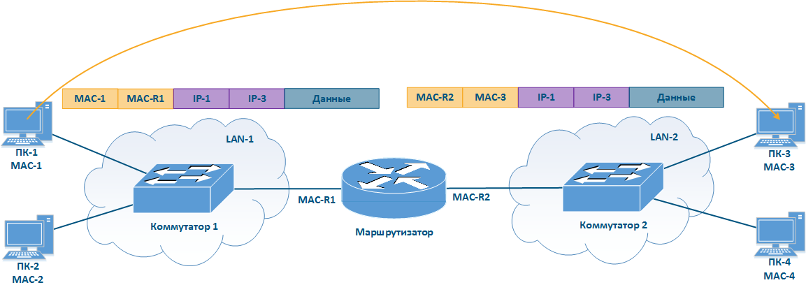
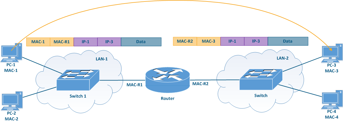
Note that the IP packet header is left unchanged, the receiver and sender MAC addresses in the Ethernet frame header are changed. This operation was performed because MAC addresses are used to transfer data within the same local network, i.e. when transferring data between different local networks, the MAC addresses will always be replaced. This data transfer mechanism is called routing.
| Center |
|---|
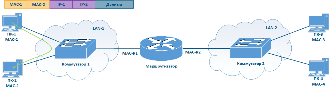
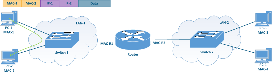
Figure 1a - Example of data transmission from PC-1 to PC-2
Figure 1b - Example of data transmission from PC-1 to PC-3 |
...
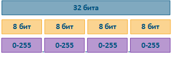
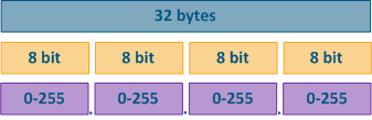
The IP protocol provides for using 32 bits for addressing nodes in the network, which are usually divided into four octets and written in decimal form, separating octets with dots (Fig. Figure 2). IP addresses examples:
- 10.94.200.7
- 192.17.0.0
- 201.15.2.255
| Center |
|---|
Figure 2 - IP address structure |
...
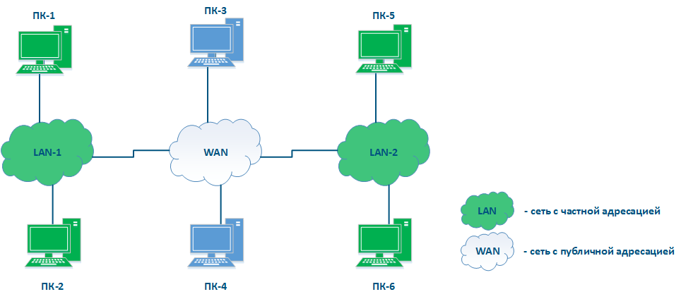
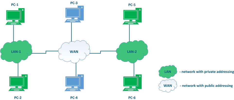
In addition to public and private addresses, several service ranges are allocated, for example, to transmit multicast traffic, loopback interface traffic, etc.
| Center |
|---|
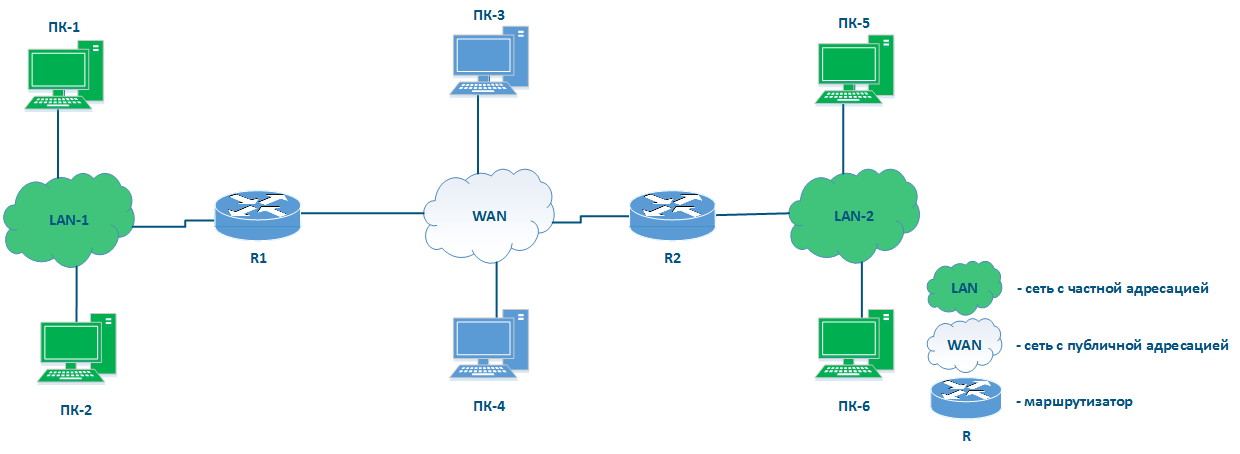
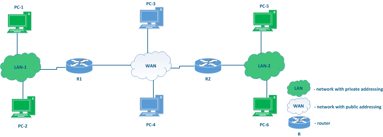
Figure 3 - An example of various types networks connecting |
...
Place of the router in the network
There is no elements on Figure 3 does not have the elements to connect networks to each other and to transfer data between networks using IP addressing. Such elements are called routers (Figure 4). Usually, a router connects several networks of an arbitrary type, not just public and private, as shown in the example.
...
- The main function of a router is to transfer data between the connected networks.
- The router is connected to the network by connecting one of the router's interfaces to the network and assigning an IP address from the allowed range to this interface. Both physical and virtual interfaces can be used.
- When transmitting data, the router is guided by routing table.
- Data within the network are transmitted using switching technology, and between networks - routing, i.e. IP and Ethernet are complement each other, as mentioned before.
- For user data, the router is an intermediate device and does not change the source and destination addresses. The packet source sets the source and destination IP addresses.
- The router analyzes only the destination address to find a destination in the routing table. The source address in the service header is set to allow the recipient to send a response packet.
- The routing table is not only in specialized network devices, but also at end nodes. For example, on a Windows software controlled PC, the routing table can be displayed by running the "route print" command at the command line.
| Center |
|---|
Figure 4 - Place of the router in the network |
...
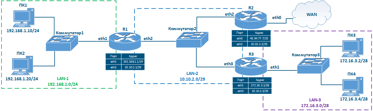
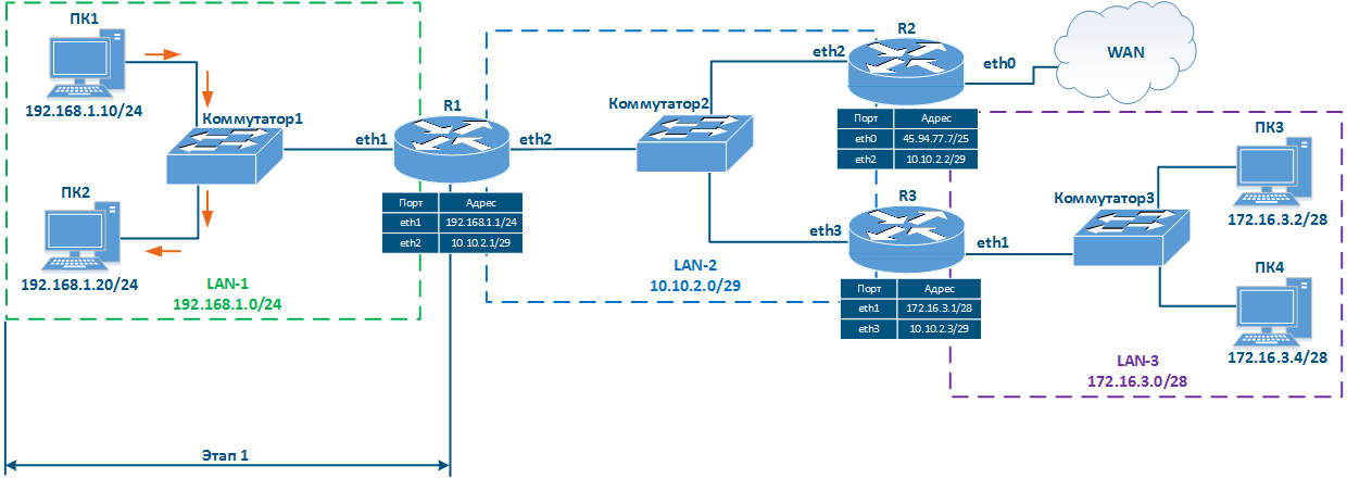
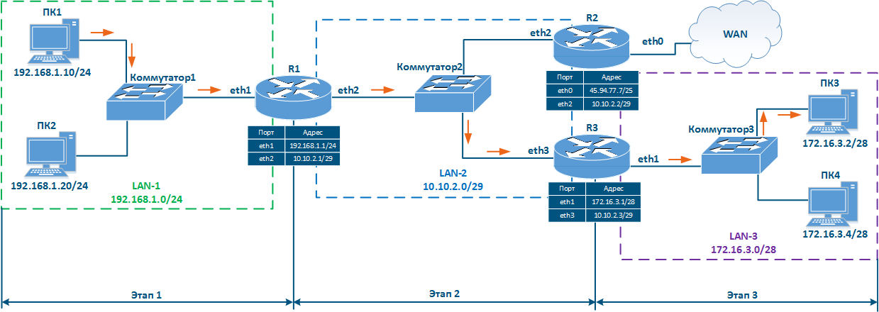
- Local network LAN-1 to connect network devices PC-1 and PC-2:
- 192.168.1.0/24 addressing is used in the network;
- 192.168.1.10/24 is assigned to PC-1;
- 192.168.1.20/24 is assigned to PC-2;
- 192.168.1.1/24 is assigned to R1.
- Local network LAN-3 to connect network devices PC-3 and PC-4:
- 172.16.3.0/28 addressing is used in the network;
- 172.16.3.2/28 is assigned to PC-3;
- 172.16.3.4/28 is assigned to PC-4;
- 172.16.3.1/28 is assigned to R3.
- Local network LAN-2 to connect routers R1, R2 and R3 with each other:
- 10.10.2.0/29 addressing is used in the network;
- 10.10.2.1/29 is assigned to R1;
- 10.10.2.2/29 is assigned to R2;
- 10.10.2.3 is assigned to R3.
- R2 router connection to the WAN global network:
- 45.94.77.7/25 is assigned to eth0 interface connected to WAN.
| Center |
|---|
Figure 5 - Network diagram example |

...
| Center | |||||||||||||||||||||||||||||||
|---|---|---|---|---|---|---|---|---|---|---|---|---|---|---|---|---|---|---|---|---|---|---|---|---|---|---|---|---|---|---|---|
Table 3 - Distance values depending on route source |


...
Data are transmitted within the same network using switching technologies, router R1 does not participate in this process.
| Center |
|---|
Figure 6a - Packet transmission from PC1 to PC2 |

...
- Step 1a: PC1 generates a packet with the PC3 destination address and sends it for processing to the L2 layer of the network interface.
- Step 1b: The L2 layer of the PC1 network interface verifies that the destination belongs to the source network. PC1 and PC3 belong to different networks, so the R1 router MAC address is set in the Ethernet header as the destination MAC address. The generated frame is sent to Switch1.
- Step 1c: Switch1 transmits frame to R1 in accordance with the switching table.
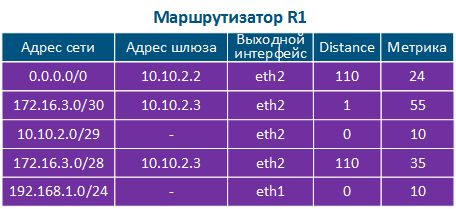
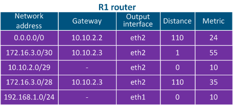
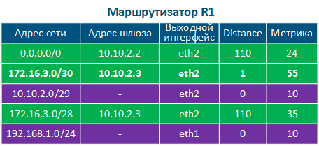
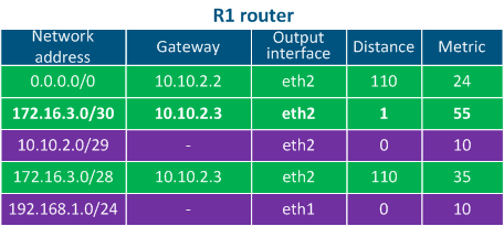
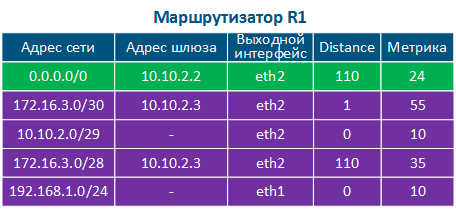
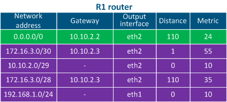
- Step 2a: Router R1 goes through the routing table: two entries match the destination address, 172.16.3.0/28 and 172.16.3.0/30. Since mask /30 is narrower than /28, R1 will redirect the packet to the 172.16.3.0/30 network. Note that if the packet destination were PC4, a different entry in the routing table would be used, even though PC3 and PC4 belong to the same network.
- Step 2b: R1 router forwards the Ethernet frame to R3 router. Source and destination IP addresses remain unchanged, as a source MAC address is set the eth2 R1 MAC address, as destination MAC address - the eth3 R3 MAC address.
- Step 2c: The switch forwards the received Ethernet frame to router R3.
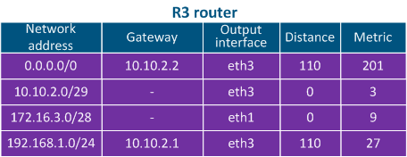
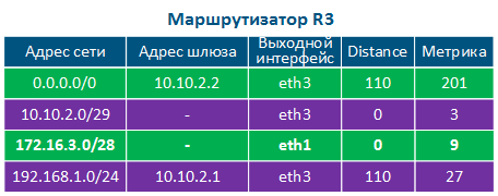
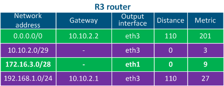
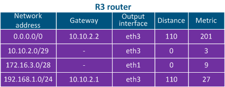
- Step 3a: Router R3 goes through the routing table: the destination address matches the 172.16.3.0/28 network.
- Step 3b: Router R3 sends an Ethernet frame to Switch3.The source and destination IP addresses remain unchanged, as a source MAC address is set the eth1 R3 interface MAC address, as the destination MAC address - the PC3 network interface MAC address.
| Center | |||||||||||||||||
|---|---|---|---|---|---|---|---|---|---|---|---|---|---|---|---|---|---|
Figure 6b - Packet transmission from PC1 to PC3
|


...
- Step 1: PC1 generates a packet with the destination address 82.151.200.119 (the IP address of the server where the infinetwireless.com website is available). The packet is sent to router R1.
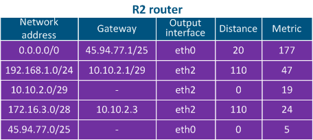
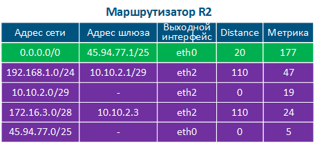
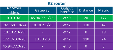
- Step 2: R1 router goes through the routing table: there are no networks in the table that match the destination address, so the default route should be used. The router sends the packet to R2.
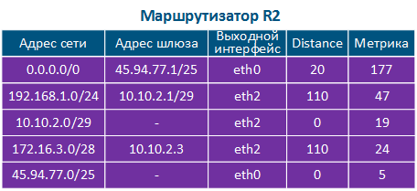
- Step 3: R2 router goes through the routing table: there are no entries matching the destination address, so the default route is used and the packet is sent to a router outside the local network (WAN).
| Center | |||||||||||||||||
|---|---|---|---|---|---|---|---|---|---|---|---|---|---|---|---|---|---|
Figure 6c - The packet transmission from PC1 to infinetwireless.com server
|


...
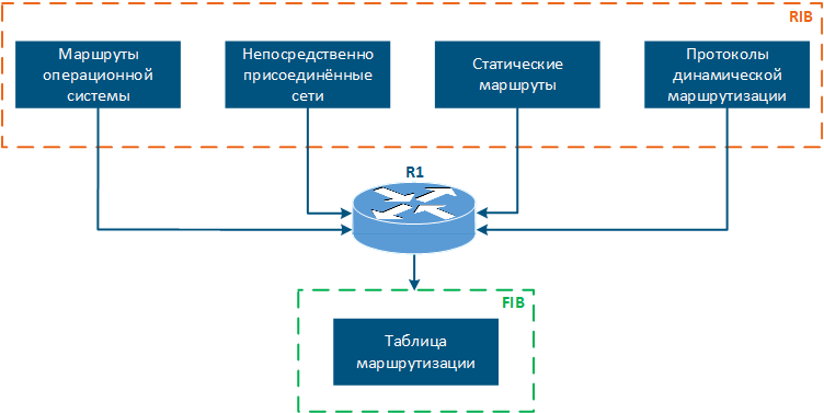
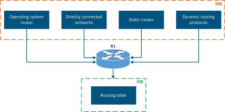
- Operating system routes: service networks used by the device operating system. For example, the loopback interface network 127.0.0.0/8.
- Directly connected networks: networks to which the device is connected directly, i.e. device interfaces are associated with IP addresses that belong to these networks. A Distance parameter of such routes is minimal and equals to 0 (Table 2a-c).
- Static routes: routes added to the table manually. Distance of such routes is equal to 1 (Table 2a).
- Dynamic routing protocols: routes obtained using dynamic routing protocols. A Distance value is assigned to each dynamic routing protocol, examples are shown in Table 3.
| Center |
|---|
Figure 7 - Routing information sources |
...
| Center | |||||||
|---|---|---|---|---|---|---|---|
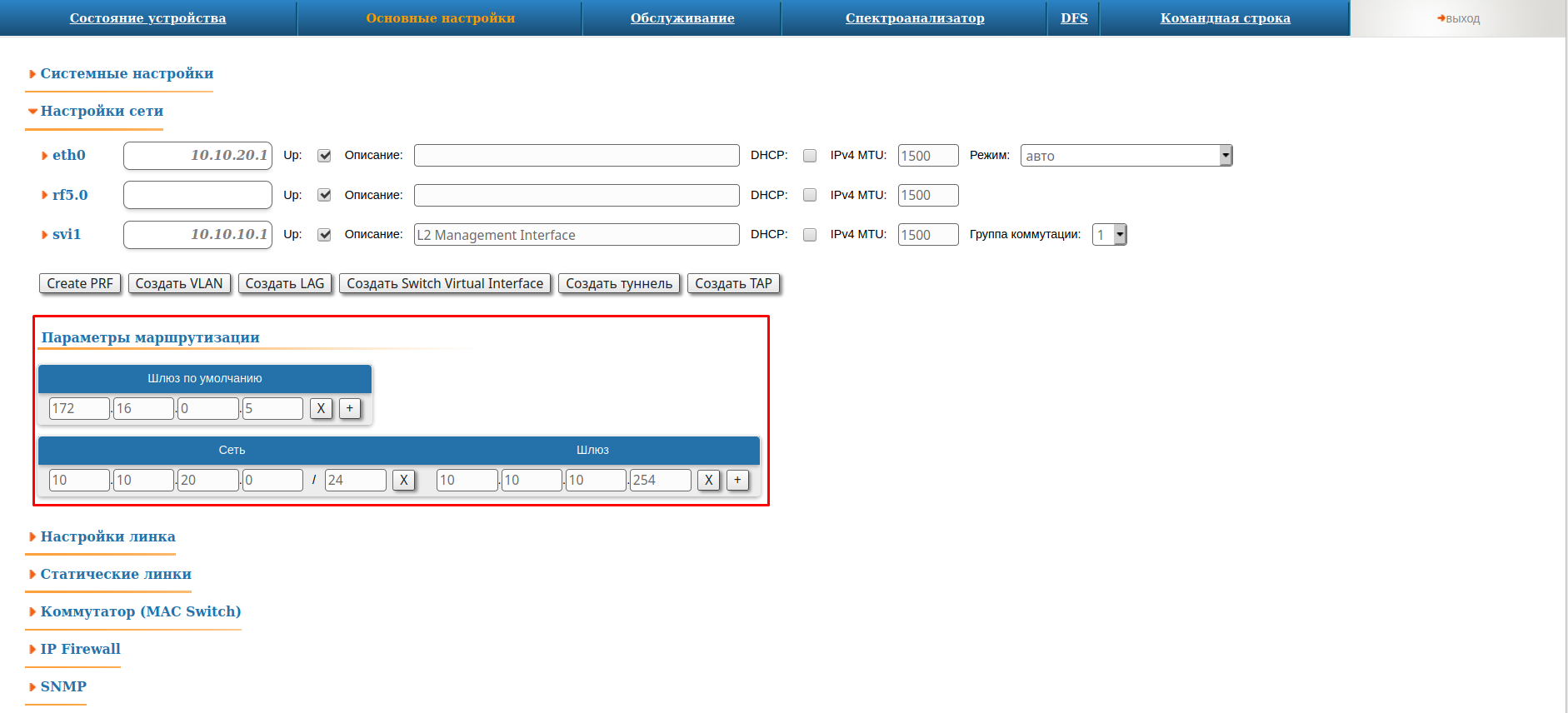
Figure 8a - An example of routing information output for the InfiLINK 2x2, InfiMAN 2x2 families devices |
...
| Center | |||||||
|---|---|---|---|---|---|---|---|
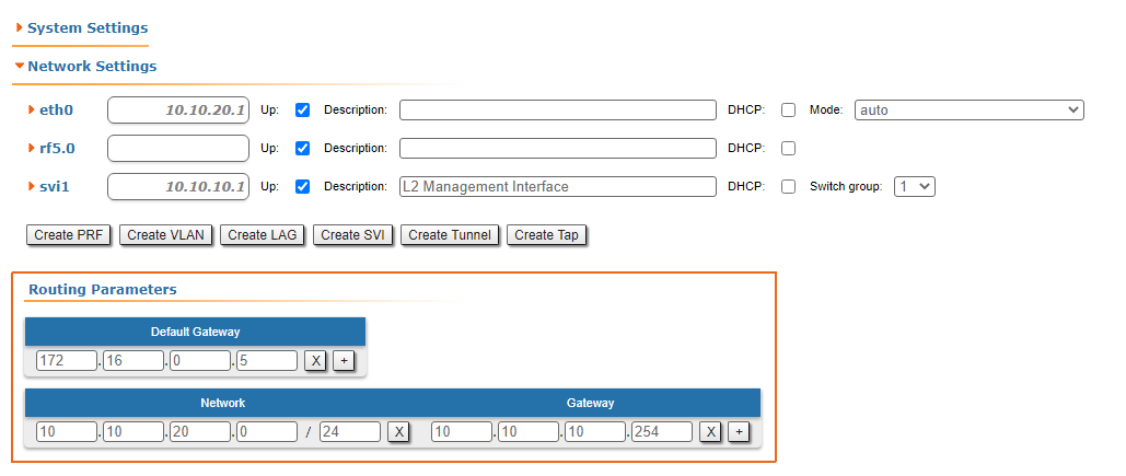
Figure 8b -An example of routing information output for the InfiLINK XG, InfiLINK XG 1000 families devices |
...
| Center | |||||||
|---|---|---|---|---|---|---|---|
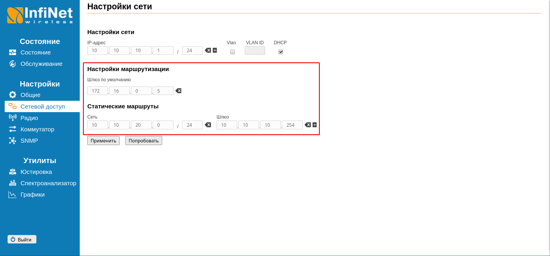
Figure 8c - An example of routing information output for the Quanta 5, Quanta 70 families devices |
...