| Include Page | ||||
|---|---|---|---|---|
|
| Hide_comments |
|---|
| Table of Contents | ||
|---|---|---|
|
Проверка настроек радио
Предварительная настройка в лабораторных условиях
...
Checking the radio settings
Pre-configuration in the lab
Before installing the devices on site, we recommend to configure the basic parameters in the lab and to make sure that the link is establishing. Step-by-step instructions for a wireless link configuration are given in the "Setting up a basic PtP link" article. We also recommend to review the "InfiLINK 2x2 / InfiMAN 2x2: Initial Link Configuration and Installation" online course.
| Note | ||
|---|---|---|
| ||
При настройке устройств в лабораторных условиях следует учесть следующие требования:
|
Проверка параметров радио
Если беспроводной канал связи не устанавливается в лабораторных условиях: убедитесь, что параметры радио установлены в значения, определённые на этапе планирования беспроводной сети, корректную конфигурацию устройств можно получить воспользовавшись Генератором конфигураций на сайте Академии Инфинет. Для установки канала связи, одно из устройств должно выступать в роли Ведущего, второе (все абоненты базовой станции при топологии точка-многоточка) - в роли Ведомого. Следующие параметры должны быть идентичны на обоих устройствах:
- Ширина канала.
- Частота (может быть в значении "авто").
- Режим Greenfield.
- SID сети.
- Ключ доступа.
Web-интерфейс
...
| |
During the configuration of the devices in a lab, take into account the following requirements:
|
Checking the radio parameters
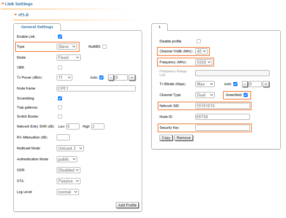
If the wireless link is not establishing in lab conditions, make sure that the radio parameters are set to the values determined during the planning stage. The correct configuration of the device can be obtained using the Configuration Generator tool found on the IW Academy website. To establish a wireless link, one device must be configured as Master, the second (or all subscribers of the base station in the point-to-multipoint topology) as Slave. The following parameters must be identical on both devices:
- Channel Width.
- Frequency ("auto" settings are possible).
- Greenfield mode.
- Network SID.
- Security Key.
Web interface
To check the wireless link parameters go to the "Basic settings" - Link settings" section. Make sure that the "Enable Link" checkbox is on.
| Center | |||||
|---|---|---|---|---|---|
|

Интерфейс командной строки
...
|
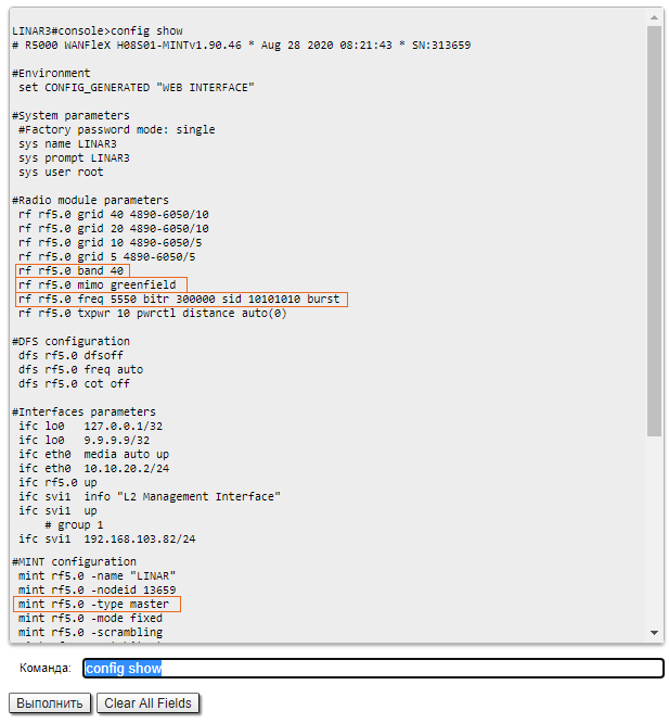
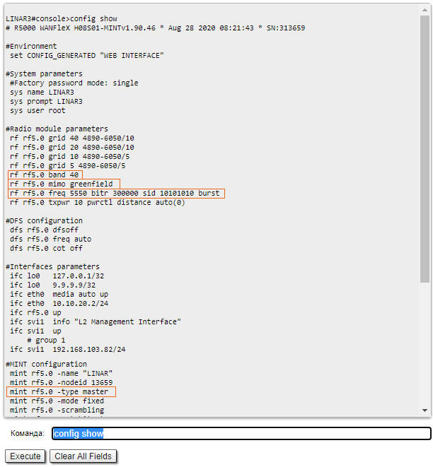
Command line interface
Use the "config show" command to check the configuration via the CLI.
| Center | |||||
|---|---|---|---|---|---|
|
Проверка статуса радиоинтерфейса
...
|
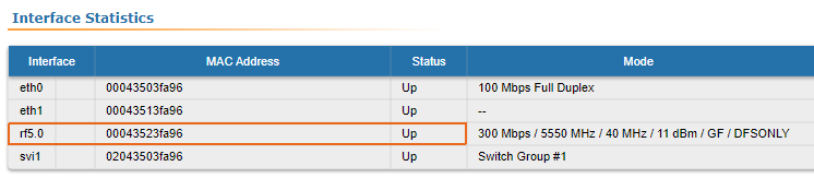
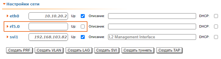
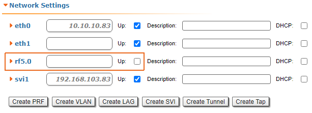
Checking the status of the radio interface
Make sure that the radio interfaces of both devices are in the "Up" state.
| Center | |||||
|---|---|---|---|---|---|
|

...
|
If the status of the interface is "Down", активируйте радио интерфейс в разделе "Настройки сети" поставив соответствующий флажокenable the radio interface in the "Network settings" section by clicking the checkbox.
| Center | |||||
|---|---|---|---|---|---|
|
...
Проверка версии ПО
Web-интерфейс
...
|
If the device does not have a radio interface, the reason for such behavior can be the recovery mode present during the reset of the device using the ERConsole. Complete the recovery process by returning the device to the factory settings from the Maintenance section.
Pay attention to the red values of the parameters in the interface statistics "Mode" column:
- Operating frequency - red value of this parameter indicates an absence of data transmission due to the spectrum scanning by the DFS tool;
- TX Power - red value for this parameter may indicate a problem with the transceiver's hardware.
Checking the firmware version
Web interface
In the "Maintenance" section, make sure that the same software version is installed on both devices: MINT or TDMA. Instructions for switching between the MINT and TDMA software versions are available in the article "How to upgrade your network from MINT to TDMA". We recommend to update the devices to the latest beta software version.
| Center | |||||
|---|---|---|---|---|---|
|
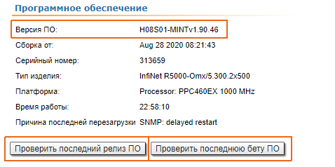
Последние версии ПО могут быть скачаны с официального FTP-сервера компании "Инфинет".
Интерфейс командной строки
Для выполнения загрузки программного обеспечения посредством командной строки, воспользуйтесь командой "flashnet", описанной в статье "Общие команды".
Проверка соответствия требованиям размещения устройств
Проверка сетевой инфраструктуры
Если канал связи не устанавливается после монтажа на площадке, убедитесь, что устройства не были повреждены в процессе транспортировки, проверьте целостность сетевой инфраструктуры, кабелей и источников питания.
Соответствия требованиям размещения
...
|

The latest software versions can be downloaded from the official InfiNet FTP server.
Command line interface
To upload the software via the command line, use the "flashnet" command described in the "General Purpose Command Set" article.
Checking the installation requirements
Checking the network infrastructure
If the link is not established after the installation on site, make sure that the devices were not damaged during shipping, check the integrity of the network infrastructure, the cables and the power supplies.
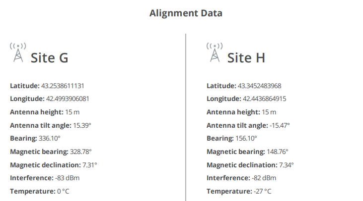
Checking the installation requirements
Check if the suspension height, azimuth and elevation of the antenna match with the values obtained from InfiPLANNER. Make sure that the obstacles on the path profile are not higher than those specified during the planning phase.
| Center | |||||
|---|---|---|---|---|---|
| Note | |||||
| |||||
Сканирование спектра рекомендуется запускать одновременно на обоих устройствах, чтобы избежать искажения картины за счёт сигнала, принимаемого от удалённого устройства
|

Поиск помех
Web-интерфейс
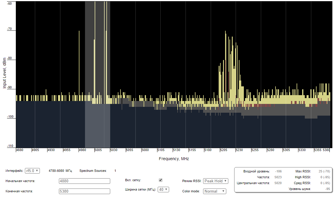
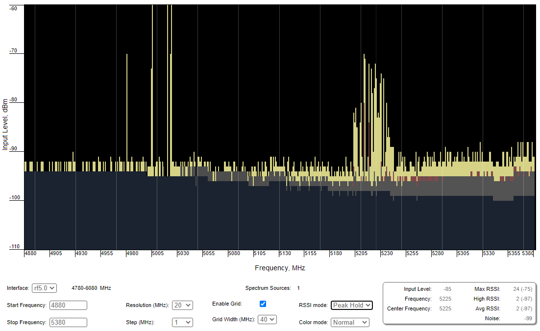
Используя встроенный инструмент "Спектроанализатор" просканируйте эфир с обеих сторон канала связи, чтобы убедиться в отсутствии помехи, способной препятствовать установке беспроводного соединения, на рабочей частоте устройств и на смежных частотах. Текущая модуляция (скорость передачи данных) будет выбрана устройством в зависимости от соотношения принимаемого сигнала от удалённого устройства к шуму и помехе (CINR). Для работы на высших модуляциях параметр CINR должен быть больше или равен 28 дБ. Получить точную информацию о интересующей частоте можно наведя на неё курсором мыши. В всплывающем окне снизу доступна информация о частоте, уровне шума (в дБм), максимальном зафиксированном уровне сигнала (Max RSSI), среднем уровне сигнала (Сред. RSSI). Показатель "High RSSI" позволяет оценить количество источников сигнала, если значение существенно отличается от показателя среднего RSSI, то источников помех несколько. Показатели отображают уровень сигнала в дБ, в скобочках указан сигнал в дБм.
|
Interference detection
Web interface
Using the built-in Spectrum Analyzer tool, scan the air on both sides of the link to make sure there is no interference that could corrupt the signal on the device's operating frequency and on the adjacent frequencies. The current modulation (bit rate) will be selected by the device depending on the carrier to interference and noise ratio (CINR). To operate at higher modulations, the CINR parameter must be greater or equal to 28 dB. To get accurate information about the frequency, hover the mouse cursor over it. The pop-up window below provides information about frequency, noise level (in dBm), maximum signal level (Max RSSI), average signal level (Average RSSI). The "High RSSI" indicator allows to estimate the number of signal sources. If the value differs significantly from the average RSSI, then there are several interference sources. The indicators show the signal level in dB, while the signal in dBm is indicated in parentheses.
| Note | ||
|---|---|---|
| ||
It is recommended to run the spectrum scanning simultaneously on both devices to avoid a misrepresentation due to the signal received from the remote device. |
...
| Center | |||||
|---|---|---|---|---|---|
|
Интерфейс командной строки
|
Command line interface
The radio environment analysis is also available via the command line using the "muffer sensor" command.