...
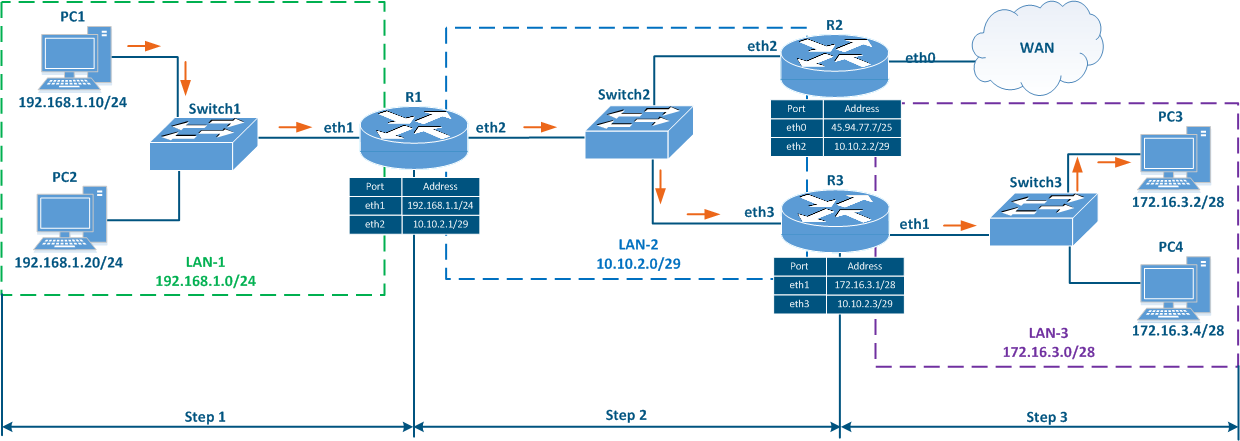
- Step 1a: PC1 generates a packet with the destination IP address of PC2 and transfers it . The routing table is checked to find a matching network and PC1 determines that PC2 is part of the same directly connected network. The packet is transferred for processing to the L2 layer of the network interface.
- Step 1b: The L2 layer of the PC1's network interface verifies to which sends an ARP request to find the MAC address that is mapped associated with the destination IP address by checking the switching table (when the first frame is transmitted towards a destination, the ARP protocol is used for determining the MAC address). Since PC1 and PC2 belong to the same network, the PC2's network interface MAC address is set in , basically the MAC of PC2. The newly discovered MAC address of PC2 is set in the Ethernet header. The generated frame is sent to Switch1.
- Step 1c: The switch transmits the frame to PC2 according to the switching table.
Data is transmitted using switching technologies within the same network, so router R1 does not participate in this process.
...
Scenario 2 - checking the availability of PC3 from PC1 (source - 192.168.1.10, destination - 172.16.3.2)
...
)
- Step 1a: Layer 3 processing: PC1 generates a packet with the destination IP address of PC3. Also, PC1 checks its routing table to find a matching network for the destination IP address. Here it finds that the best match is network 172.16.3.0/28 which is associated with the gateway (next hop IP address) 192.168.1.1/24 ( the IP address of R1's eth1 interface). Then, the packet is sent for processing to the L2 layer of the network interface.
- Step 1b: The L2 layer of the PC1's network interface verifies that the destination belongs to the source network. PC1 and PC3 belong to different networks, so the R1 router MAC address sends an ARP request to determine the MAC address corresponding to the gateway IP (the MAC of R1's eth1 interface). The MAC address of the R1's eth1 interface is set in the Ethernet header as the destination MAC address. The generated frame is sent to Switch1.
- Step 1c: Switch1 transmits the frame to R1 in accordance with according to the switching table.
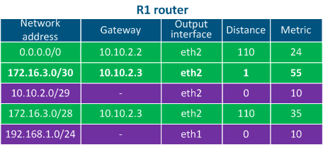
- Step 2a: Router R1 goes through the checks its own routing table: two entries match the destination address, 172.16.3.0/28 and 172.16.3.0/30. Since mask /30 is narrower than /28, R1 will redirect the packet to the 172.16.3.0/30 network. Note that if the packet destination were PC4, a different entry in the routing table would be used, even though PC3 and PC4 belong to the same network.
- Step 2b: Router R1 router forwards the Ethernet frame to towards router R3 router. Source The source and destination IP addresses remain unchanged, as a while the new source MAC address is set the eth2 R1 MAC address, as destination MAC address - the eth3 R3 MAC addressone of R1's eth2 interface and the new destination MAC address is the one of the R3's eth3 interface, determined also through the ARP process using the gateway IP address (IP of the R3's eth3 interface).
- Step 2c: The switch forwards the received Ethernet frame Switch 2 receives the frame and forwards it to router R3 according to its switching table.
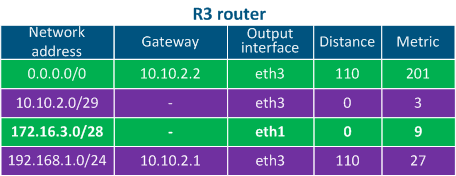
- Step 3a: Router R3 goes through the checks its own routing table: the destination address matches with the 172.16.3.0/28 network which is directly connected to it so it does not need a gateway IP.
- Step 3b: Router R3 sends an determines through ARP the MAC address of PC3 (the destination of the packet) and sends the Ethernet frame to Switch3.The source and destination IP addresses remain unchanged, as a while the source MAC address is set the eth1 R3 interface MAC address, as the one of the R3's eth1 interface and the destination MAC address - is the PC3 network interface MAC address of PC3.
| Center | |||||||||||||||||
|---|---|---|---|---|---|---|---|---|---|---|---|---|---|---|---|---|---|
Figure 6b - Packet transmission from PC1 to PC3
|
Scenario 3 - connection with the "infinetwireless.com" from PC1 (source - 192.168.1.10, destination - 82.151.200.119)
...