...
| Tip | ||||||||||||
|---|---|---|---|---|---|---|---|---|---|---|---|---|
| ||||||||||||
|
...
Routing configuration for the data traffic
...
using a Point-to-Multipoint scheme
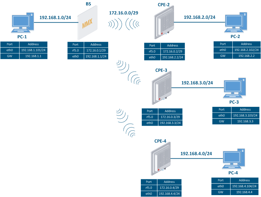
Let's look at the task of performing the routing configuration for the data traffic at the using a PtMP scheme (Figure 3). Within With this task, should be organized the connectivity between PC-1, PC-2, PC-3 and PC-4 should be established using routing, since all the PCs belong to different subnets.
| Center |
|---|
Figure 3 - Scheme of the data traffic routing configuration for the InfiLINK 2x2 , / InfiMAN 2x2 families of devices |
Let's look at the step-by-step configuration of the wireless devices using the Web interface:
...
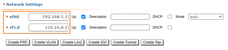
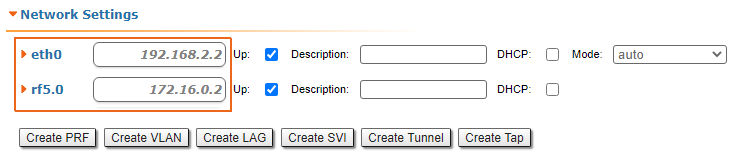
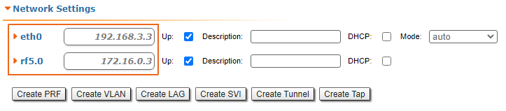
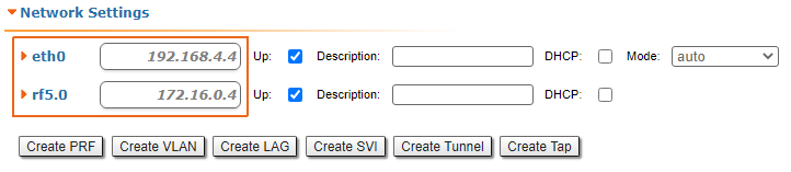
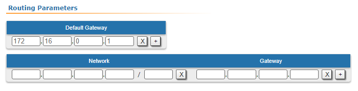
| Description | Add the IP addresses to the devices interfaces in accordance with interfaces of the devices according to the scheme. |
|---|---|
| BS |
|
| CPE2 |
|
| CPE3 |
|
| CPE4 |
|
...
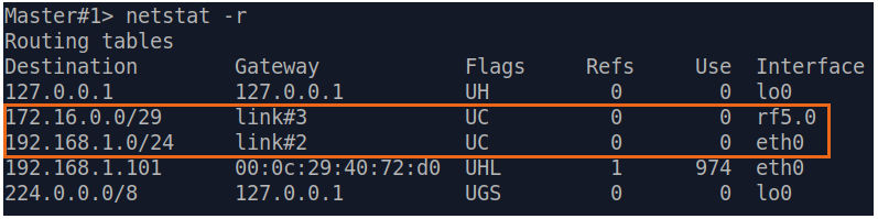
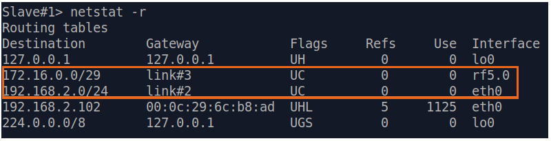
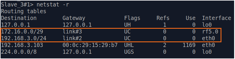
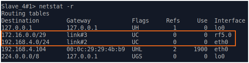
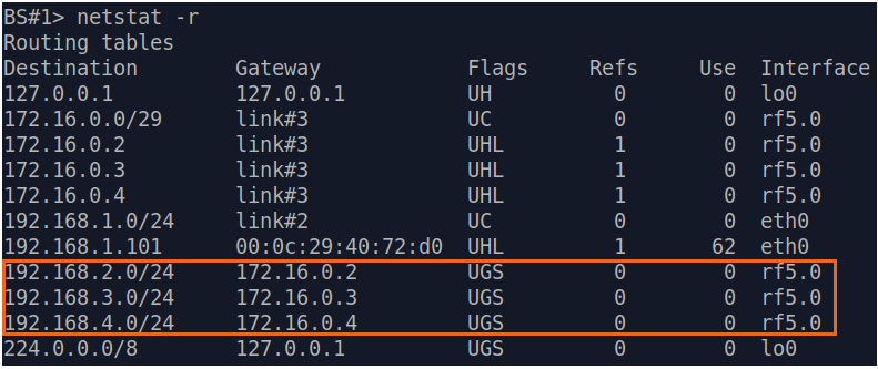
| Description | Analyze the routing table: after adding the IP addresses to the device devices' interfaces, the routing tables were filled up with entries about specifying the directly connected networks (markmarked as C). |
|---|---|
| BS |
|
| CPE2 |
|
| CPE3 |
|
| CPE4 |
|
Step 3
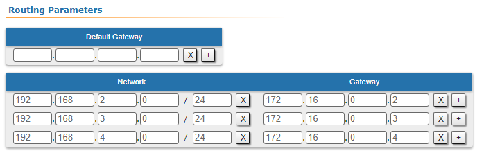
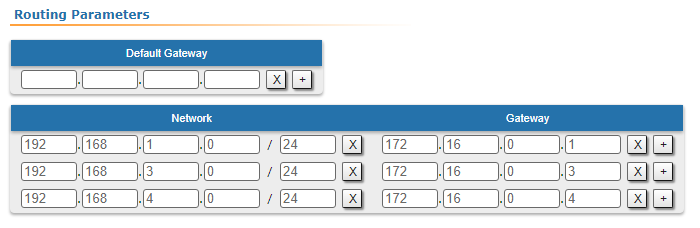
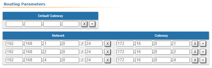
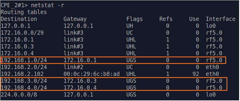
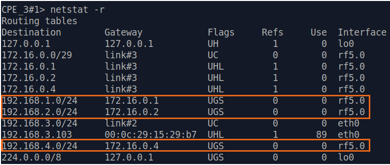
| Description | Add static routes for connection the connectivity between the PCs. Three static routes should be added on each wireless devicesdevice, for the other 3 PCs that are not directly connected. |
|---|---|
| BS |
|
| CPE2 |
|
| CPE3 |
|
| CPE4 |
|

Step 3a
| Description | Since the data from any CPE to the BS or to each other go through another CPE goes through the BS, the CPEs routing tables of the CPEs can be optimized. Instead of three static entries, one default route can be added. The routing table on of the BS is not possible to optimizecannot be optimized, as the BS has separate connections with each station with no common point. |
|---|---|
| BS | - |
| CPE2 |
|
| CPE3 |
|
| CPE4 |
|
Step 4
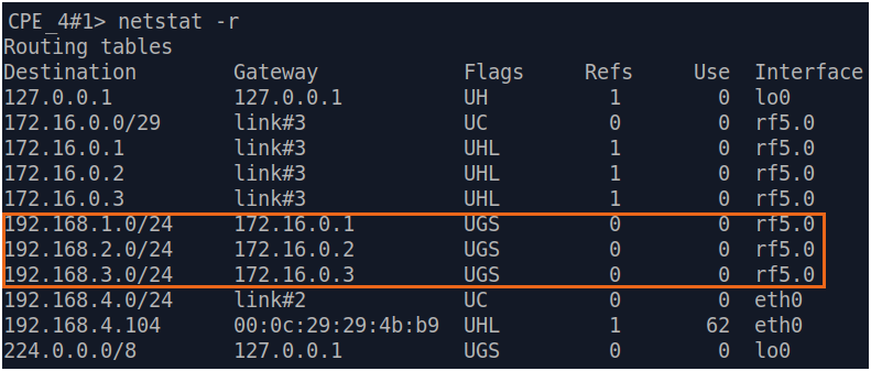
| Description | Analyze the routing table: three static entries (flag S) have been added to the routing table of each device. |
|---|---|
| BS |
|
| CPE2 |
|
| CPE3 |
|
| CPE4 |
|
...
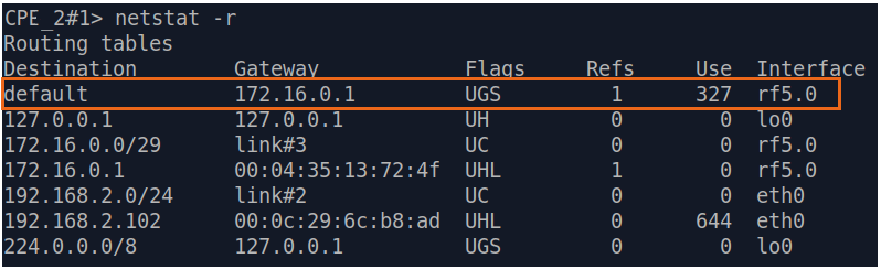
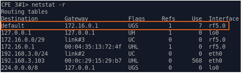
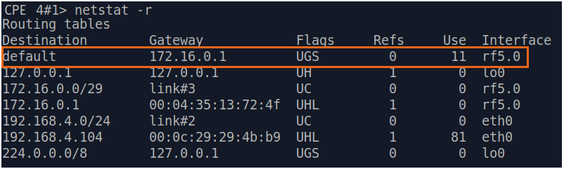
| Description | If a default route was added in step 3a, a corresponding entry (flag S) will be added to the routing table. |
|---|---|
| BS | Changes are not required on the BS. |
| CPE2 |
|
| CPE3 |
|
| CPE4 |
|
Step 5
| Description | The task has been solved: the connectivity between PC-1, PC-2, PC-3 and PC-4 was successfully established. Note , that along with the data traffic routing, the management traffic routing was also organizedestablished. |
|---|
| Tip | ||||||||||||
|---|---|---|---|---|---|---|---|---|---|---|---|---|
| ||||||||||||
|
...