...
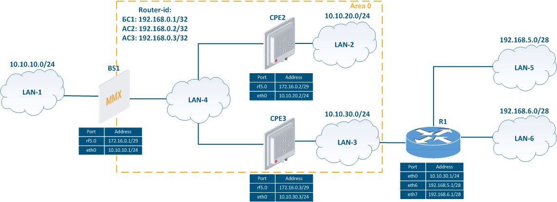
- The network consists of three wireless devices BS1, CPE2, CPE3 configured as routers.
- Wireless devices build the OSPF backbone area.
- BS1 has an external link for connecting to LAN-1 network.
- The CPE3 router is connected to the outside router R1.To make the R1 router networks available, static routes to the networks 192.168.5.0/28 and 192.168.6.0/28 have been added to CPE3.
- Routers BS1, CPE2 and CPE3 use as identifiers the addresses assigned to the loopback interface: 192.168.0.1/32, 192.168.0.2/32 and 192.168.0.3/32.
| Center |
|---|
Figure 2 - Network scheme with one OSPF area |

...
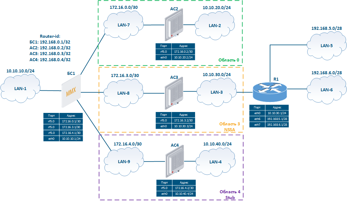
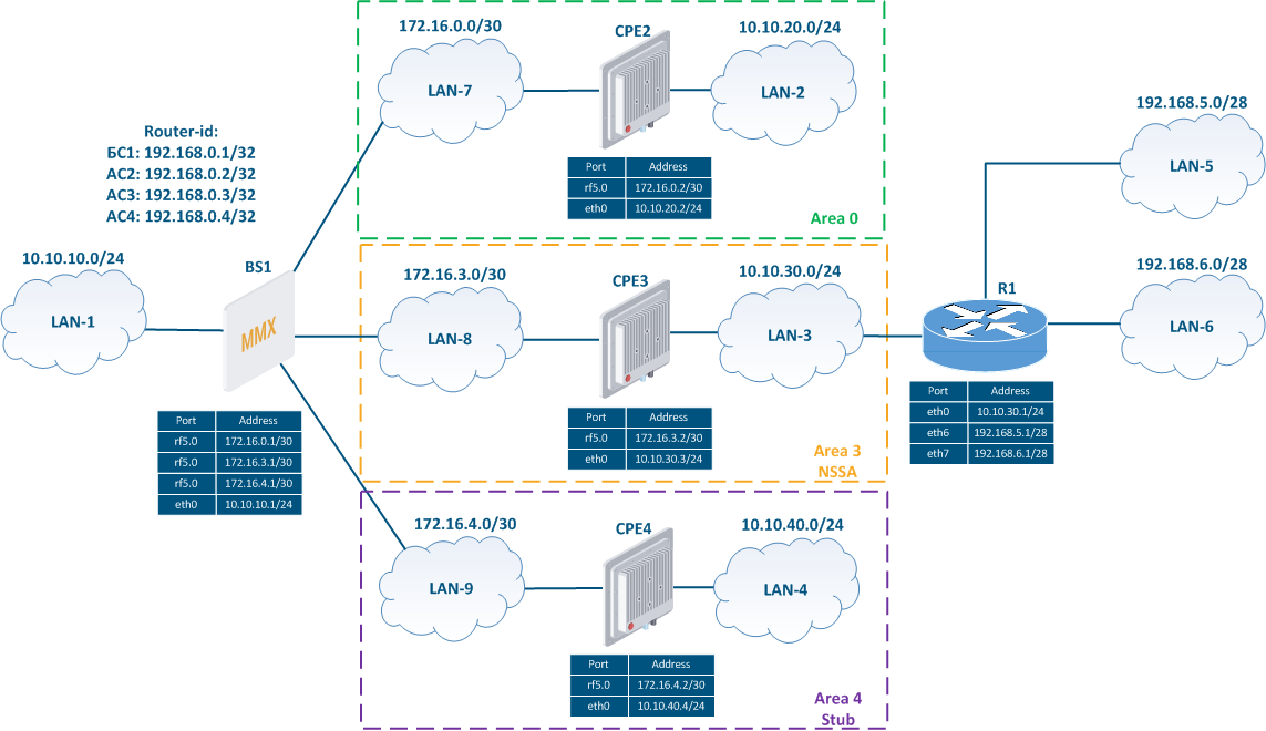
- The network consists of four wireless devices BS1, CPE2, CPE3, CPE4, configured in the router mode.
- Wireless devices creates three OSPF areas:
- area 0: routers BS1 and CPE2 are connected to the area. The BS1 router has an external link;
- area 3: routers BS1 and CPE3 are connected to the area, the area is NSSA type. CPE3 router has an external link with a outside router R1 and two static routes to networks 192.168.5.0/28 and 192.168.6.0/28;
- area 4: routers BS1 and CPE4 are connected to the area, the area is Stub type.
- Routers BS1, CPE2, CPE3 and CPE4 use the addresses assigned to the loopback interface as identifiers: 192.168.0.1/32, 192.168.0.2/32, 192.168.0.3/32 and 192.168.0.4/32.
| Center |
|---|
Figure 3 - Network scheme with several OSPF areas |
...