...
RIP (Routing Information Protocol) - is a dynamic routing protocol based on the Bellman-Ford algorithm. The protocol has the following features:
- the first RIP version was developed in 1969, as described in RFC 1058;
- the second RIP version was developed in 1994, as described in RFC 2454. This version is the main one for use used in IPv4 networks. There is no backward compatibility between the first and the second versions;
- there is a RIP version developed for IPv6 networks. This version is called RIPng and it is described in RFC 2080;
- RIP is an internal distance vector routing protocol;
- the number of hops is used as a metric, i.e. the number of routers number at on the path to the destination network. The maximum metric value is 16 , and it limits the network size where RIP can be used;
- the multicast address 224.0.0.9 is reserved for RIP version 2. The first version of the protocol uses the broadcast address 255.255.255.255;
- UDP datagrams are used for service information transmission , and port 520 is assigned to the protocol;
- the first RIP version only supports the routes to classful networks distribution, the second to classless;
- the distance value of 120 is used for RIP;
- RIP supports authentication: routing information will only be accepted from a router with having the same the key value.
RIP
...
's operational algorithm
Let's look at an example on how is the example routing information distribution distributed over a network using RIP. The example includes follows the following scheme in (Figure 1):
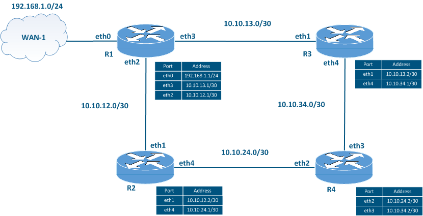
- the network consists of four routers R1, R2, R3 and R4, connected as in a ring, they forms . These routers form a RIP domain. A RIP domain is a set of routers that exchange routing information using RIP;
- router R1 has an external link to the WAN-1 network;
- an independent IP network class is assigned for each link.
RIP must be configured on all the routers. WAN-1 is the external network, i.e. the route to this network must be added to the RIP domain as external.
| Center |
|---|
Figure 1 - Network scheme used to explain the RIP operation 's operational principles |
In this example, the distribution of the routing information distribution from router R1 will be described, because the routes from the other devices will be distributed in the same way.
The RIP operation operational algorithm in the described scheme is the following:
- Start RIP starts.
- Routing information distribution.
- Adding routes to RIB.
- Adding routes to FIB.
- Timers control.
- Network changes control.
| Anchor | ||||
|---|---|---|---|---|
|
At this stage, the RIP must be enabled on the routers and must be defined the list of interfaces that will participate in the RIP operationprocess must be defined.
The network list definition is done performed using the "network A.B.C.D/M" command. All network interfaces which whose IP addresses belong to the specified range participate the in RIP. This means that the routing information will be distributed from these interfaces, and the information about the networks associated with these interfaces will be transmitted to other routers.
If an interface participates in the RIP process, but routing information should not be distributed over that interface, then the interface can be configured as passive.
...
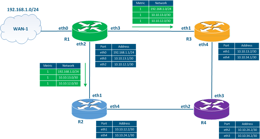
- Step 1: router R1 generates service messages with routing information. Service The service messages contain information about networks 10.10.13.0/30 and 10.10.12.0/30, since the interfaces associated with these networks are included in RIP at when the protocol starting stage. Also, is started . The service messages include also information about the 192.168.1.0/24 network, since router R1 must redistribute the external routes according to the task conditions. The metric value for each network is set to 1.
- Step 2: the router sends out the service messages generated at step 1 (Figure 2a). Distribution The distribution is performed through the eth2 and the eth3 interfaces included in RIP when the RIP at the protocol starting stageis started.
| Center |
|---|
Figure 2a - R1's routing information distribution |
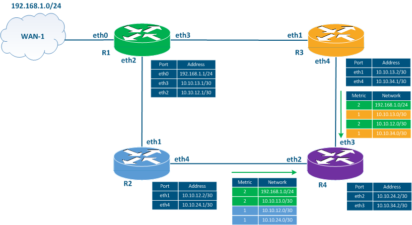
- Step 3: routers R2 and R3 generate service messages to transmit the routing information to router R4:
- R2: the router includes in the service message the 192.168.1.0/24 and the 10.10.13.0/30 networks received from router R1, incrementing the metric value. Information The information about the 10.10.12.0/30 network received from R1 is ignored because R2 is directly connected to this network. Instead, router R2 includes the 10.10.12.0/30 network with the metric 1 in the service message, announcing the network by itself. Also, the service message includes information about the network 10.10.24.0/30.
- R3: the router includes in the service message the 192.168.1.0/24 and the 10.10.12.0/30 networks received from router R1, incrementing the metric value. Information The information about the 10.10.13.0/30 network received from R1 is ignored because R3 is directly connected to this network. Instead, router R3 includes the 10.10.13.0/30 network with the metric 1 in the service message, announcing the network by itself. Also, the service message includes information about the network 10.10.34.0/30.
- Step 4: routers R2 and R3 send the service messages formed generated in the previous step to router R4 (Figure 2b). Note that R2 and R3 send routing information to R1, but this process will not be described in this example.
| Center |
|---|
Figure 2b - Routing information distribution by routers R2 and R3 |
Adding routes to the RIB
After exchanging service messages, the routers add the received routes to the RIB. In this case, some routes are filtered out. To filter the routing information, devices are guided by the following principles:
...