...
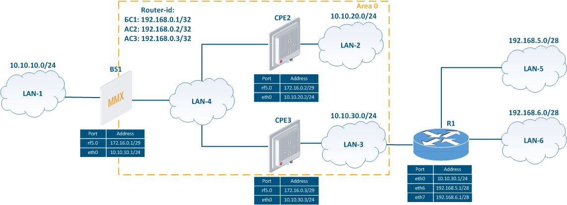
- The network consists of three wireless devices BS1, CPE2 and CPE3 configured as routers.
- The wireless devices are part of the OSPF backbone area 0 (only one OSPF area is present in this setup).
- BS1 has an external link for connecting to the LAN-1 network.
- The CPE3 router is connected to the external router R1.To make R1's router networks available, static routes to the networks 192.168.5.0/28 and 192.168.6.0/28 have been added to CPE3.
- Routers BS1, CPE2 and CPE3 use as identifiers the addresses assigned to the loopback interface: 192.168.0.1/32, 192.168.0.2/32 and 192.168.0.3/32.
| Center |
|---|
Figure 2 - Network scheme with one OSPF area |

...
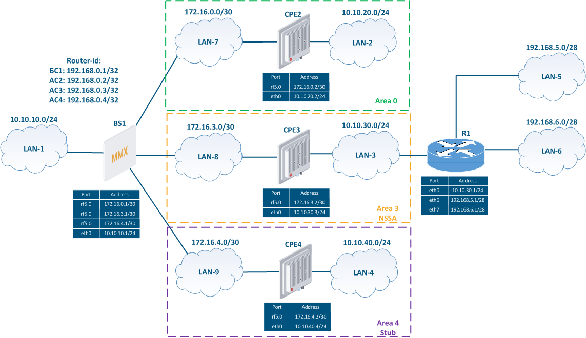
- The network consists of four wireless devices BS1, CPE2, CPE3 and CPE4, configured in the router mode.
- The wireless devices are part of three OSPF areas:
- area 0: routers BS1 and CPE2 are connected to this area. The BS1 router has an external network connection;
- area 3: routers BS1 and CPE3 are connected to this area, the area's type is NSSA. The CPE3 router has an external link with router R1 and two static routes to the networks 192.168.5.0/28 and 192.168.6.0/28;
- area 4: routers BS1 and CPE4 are connected to this area, the area's type is Stub.
- Routers BS1, CPE2, CPE3 and CPE4 use the addresses assigned to the loopback interface as identifiers: 192.168.0.1/32, 192.168.0.2/32, 192.168.0.3/32 and 192.168.0.4/32.
| Center |
|---|
Figure 3 - Network scheme with several OSPF areas |

...