...
Each RIP shell mode provides help by displaying the full list of supported commands. To display the list, use the "help" command.
The routing table can be displayed using one of the following commands:
| Code Block | ||||
|---|---|---|---|---|
| ||||
from the WANFleX cli: BS_1#1> netstat -r from the RIP basic shell mode: RIP> show route from the ARDA shell mode: ARDA> show route |
Task
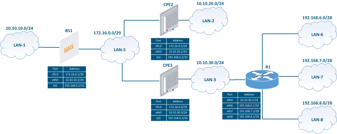
Let's take a look at the RIP step by step configuration on Infinet devices of the RIP protocol on the InfiNet devices, using the following scheme (Figure 2):
- the network consists of three wireless devices: BS1, CPE2 and CPE3 which are connected by through wireless links;
- бsubnet subnet 172.16.0.0/29 is assigned to the wireless network;
- each wireless device has a connection to a wired segment: BS1 is connected to the 10.10.10.0/24 network, CPE2 - to the 10.10.20.0/24 network, CPE3 - to the 10.10.30.0/24 network;
- three static routes are configured on the CPE3 wireless device to towards the networks 192.168.6.0/28, 192.168.7.0/28 , and 192.168.8.0/28. The third-party router R1 is used as a gateway;
- to the loopback interface of each wireless device is assigned an an IP address from the 192.168.0.0/24 network is assigned to the loopback interface of each wireless device.
Task: configure the RIP operation protocol on the wireless devices in order to add information about all the networks in the scheme to the routing table of each router. The BS1 device should be used as the default gateway on the CPE2 and CPE3 devices.
| Center |
|---|
Figure 2 - Network scheme for the RIP configuring exampleconfiguration |
Solution
Perform the The devices will be configured step by step configuration in accordance with the task-by-step. In addition to the RIP configuration, the static routing will be used (see. see Static routing) for connection providing connectivity with LAN-6, LAN-7 , and LAN-8.
To demonstrate more features in the exampleIn order to highlight several available features, different approaches will be used to configure when configuring RIP on the wireless devices.
Pre-configuration
| Description | Perform a devices preliminary configuration of the devices, consisting of the following steps:
| |||||||
|---|---|---|---|---|---|---|---|---|
| BS1 |
| |||||||
| CPE2 |
| |||||||
| CPE3 |
|
...
| Description | Configure the RIP protocol in accordance with according to the scheme. Step 1: start the RIP daemon. Step 2: define the interfaces where RIP should be started:
In the CPE2 router 's configuration, the range of networks used in RIP will be set as a single entry: 0.0.0.0/0. This entry includes all networks and enables the RIP support on all router's interfaces; when some device one of the CPE2's interfaces is connected to a new network, this network will be immediately announced via RIP. This approach doesn't require any additional RIP configuration, but decreases the control over the announcements. On the BS1 and CPE3 routers, we will be set only those networks that are associated with the interfaces participating in the RIP's operation. Step 3: make redistribution of redistribute the directly connected networks on the BS1 router and the static routes on the CPE3 router. Step 4: configure passive interfaces. The CPE3 eth0 interface of CPE3 is connected to the outside external router R1, therefore it is necessary to block the transmission of the routing information transmission between them. To ensure this, the CPE3 eth0 interface of CPE3 must be configured as passive. Step 5: announce the default route, specifying BS1 as the gateway. | |||||||
|---|---|---|---|---|---|---|---|---|
| BS1 |
| |||||||
| CPE2 |
| |||||||
| CPE3 |
|
Command output analyzing
...