Successfully pass the free certification exam at IW Academy and become an Infinet Certified Engineer.
InfiLINK 2x2 / InfiMAN 2x2
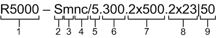
Structure items are described below
| Item | Description |
|---|---|
| 1 |
|
| 2 |
|
| 3 |
|
| 4 |
|
| 5 |
|
| 6 |
|
| 7 |
|
| 8 |
|
| 9 |
|
NOTE
Units may also be marked as “LITE” and “PRO”, where "PRO" - units that operate at greater distance and with higher performance. "LITE" refers to R5000-Smn and R5000-Lmn models, "PRO" - R5000-Mmx and R5000-Omx.
InfiLINK Evolution / Evolution

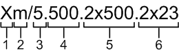
Structure items are described below
| Item | Description |
|---|---|
| 1 | Product family name:
|
| 2 | Frequency range:
|
| 3 |
|
| 4 | Antenna gain. Base Station Sectors:
Subscriber Terminals and PTP devices:
|
| 5 | Additional options:
|
InfiLINK XG / InfiLINK XG 1000
Structure items are described below
| Item | Description |
|---|---|
| 1 |
|
| 2 |
|
| 3 |
|
| 4 |
|
| 5 |
|
| 6 |
|
Quanta 5 / Quanta 6

Structure items are described below
| Item | Description |
|---|---|
| 1 | Product family name:
|
| 2 | Frequency range:
|
| 3 | Antenna gain:
|
| 4 | Additional options:
|
NOTE
Previously, device part numbers contained decimal number with the following structure:
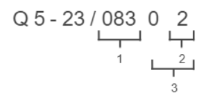
- Hardware version.
- Options:
- 0 - models with GigabitEthernet port and supporting 40 MHz channel width;
- 1 - models with GigabitEthernet port and supporting 50 and 56 MHz channel widths;
- 2 - models with Combo port GigabitEthernet/SFP and supporting 50 and 56 MHz channel widths.
Firmware version:
Quanta 70
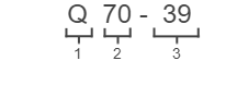
Structure items are described below
| Item | Description |
|---|---|
| 1 | Product family name:
|
| 2 | Frequency range:
|
| 3 |
|