Attention
Configurations from the scenarios below are examples that demonstrate the potential capabilities of Infinet devices. The configuration may change depending on the model and firmware version. Do not recommend copying the solution data to the hardware without checking.
Description
It is easy to fully reserve a connection by combining two radio channels into one MINT domain. If you configure the aggregation of channels, you can increase the maximum throughput of the entire radio link.
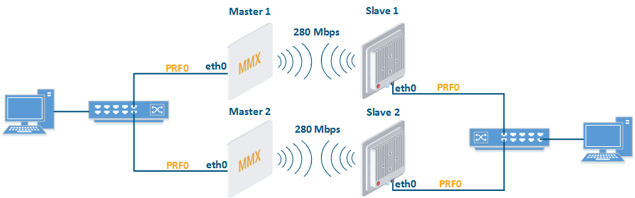
Conceptual scheme
Example
A management is VLAN 100 inside a switch group 100. A transport of user data is inside switch groups 1 and 2.
Create first radio link
Master 1rf rf5.0 band 40 rf rf5.0 mimo rf rf5.0 freq 5000 bitr 300000 sid 10101010 burst rf rf5.0 txpwr 25 pwrctl distance auto dfs rf5.0 dfsoff mint rf5.0 -roaming leader mint rf5.0 -type master mint rf5.0 -name "Master 1" mint rf5.0 -key "123456789" mint rf5.0 poll start ifc svi100 up ifc vlan100 vlan 100 vlandev eth0 up sw group 100 add vlan100 rf5.0 svi 100 group 100 ifc svi100 192.168.1.1/24 sw group 100 stp on sw group 100 start
Slave 1rf rf5.0 band 40 rf rf5.0 mimo rf rf5.0 burst dfs rf5.0 dfsoff mint rf5.0 prof 1 -band 40 -freq 5000 -bitr 300000 -sid 10101010 -nodeid 00020 -type slave -netid 0 -minbitr 30000 -autobitr -mimo -key "123456789" mint rf5.0 -name "Slave 1" ifc svi100 up ifc vlan100 vlan 100 vlandev eth0 up sw group 100 add vlan100 rf5.0 svi 100 group 100 ifc svi100 192.168.1.2/24 switch group 100 order 1 sw group 100 stp on sw group 100 start
Configure second radio link
Master 2rf rf5.0 band 40 rf rf5.0 mimo rf rf5.0 freq 5100 bitr 300000 sid 10101010 burst rf rf5.0 txpwr 25 pwrctl distance auto dfs rf5.0 dfsoff mint rf5.0 -roaming leader mint rf5.0 -type master mint rf5.0 -name "Master 2" mint rf5.0 -key "123456789" mint rf5.0 poll start ifc svi100 up ifc vlan100 vlan 100 vlandev svi100 up ifc vlan100 192.168.1.3/24 sw group 100 add prf0 svi 100 group 100 sw group 100 stp on sw group 100 start
Slave 2rf rf5.0 band 40 rf rf5.0 mimo rf rf5.0 burst dfs rf5.0 dfsoff mint rf5.0 prof 1 -band 40 -freq 5100 -bitr 300000 -sid 10101010 -nodeid 00040 -type slave -netid 0 -minbitr 30000 -autobitr -mimo -key "123456789" mint rf5.0 -name "Slave 2" ifc svi100 up ifc vlan100 vlan 100 vlandev svi100 up ifc vlan100 192.168.1.4/24 sw group 100 add prf0 svi 100 group 100 sw group 100 stp on sw group 100 start
Configure switches (Switch configuration is not included in this example)
Create united MINT domain
Master 1ifc prf0 up prf 0 parent eth0 mint prf0 -name "Master 1 prf" mint prf0 -nodeid 00050 mint prf0 -type master mint prf0 -mode fixed mint prf0 -key "123456789" mint prf0 -authmode public mint prf0 start mint join rf5.0 prf0
Slave 1ifc prf0 up prf 0 parent eth0 mint prf0 -name "Slave 1 prf" mint prf0 -nodeid 00060 mint prf0 -type master mint prf0 -mode fixed mint prf0 -key "123456789" mint prf0 -authmode public mint prf0 start mint join rf5.0 prf0
Master 2ifc prf0 up prf 0 parent eth0 mint prf0 -name "Master 2 prf" mint prf0 -nodeid 00070 mint prf0 -type master mint prf0 -mode fixed mint prf0 -key "123456789" mint prf0 -authmode public mint prf0 start mint join rf5.0 prf0
Slave 2ifc prf0 up prf 0 parent eth0 mint prf0 -name "Slave 2 prf" mint prf0 -nodeid 00080 mint prf0 -type master mint prf0 -mode fixed mint prf0 -key "123456789" mint prf0 -authmode public mint prf0 start mint join rf5.0 prf0
Configure switch groups
Attention
The number of the switching group for data transmission on Master 2 and Slave 2 devices must differ from the number of such a group on the devices Master1 and Slave 1
Master 1switch group 1 add eth0 prf0 sw group 1 repeater on switch group 1 start
Slave 1switch group 1 add eth0 prf0 sw group 1 repeater on switch group 1 start
Master 2switch group 2 add eth0 prf0 sw group 2 repeater on switch group 2 start
Slave 2switch group 2 add eth0 prf0 sw group 2 repeater on switch group 2 start