General description
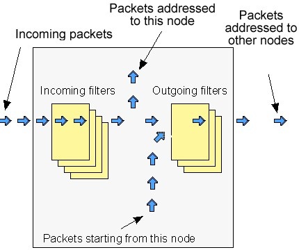
IP Firewall is a mechanism of filtering packets crossing an IP network node, according to different criteria. System administrator may define a set of incoming filters (addincoming) and a set of outgoing filters (addoutgoing). The incoming filters determine which packets may be accepted by the node. The outgoing filters determine which packets may be forwarded by the node as a result of routing.
Each filter describes a class of packets and defines how these packets should be processed (reject and log, accept, accept and log).
Packets can be filtered based on the following criteria:
- Protocol (IP, TCP, UDP, ICMP, ARP);
- Source address and/or destination address (and port numbers for TCP and UDP);
- The network interface it arrived on;
- Whether the packet is a TCP/IP connection request (a packet attempting to initiate a TCP/IP session) or not;
- Whether the packet is a head, tail or intermediate IP fragment;
- Whether the packet has certain IP options defined or not;
- The MAC address of the destination station or of the source station.
Below figure illustrates how packets are processed by the filtering mechanism of the router.
There are two classes (sets) of filters - prohibiting (reject) and permitting (accept).
Furthermore, a filter may be applied to all inbound packets or only to packets arriving via a specific interface.
Each received packet is checked against all filters in the order they are put in the set.
The first filter that matches the received packet determines how the packet will be treated. If the filter is an accept filter, the packet is accepted, otherwise it is rejected. If the packet matches no filter in the set, or if the set is empty, the packet is accepted.
CAUTION
The rejected packet will be discarded without notification to the sender.
Filters are defined using the "ipfw" command. For example, a command
ipfw add reject all from 192.168.5.3 to 192.168.11.7
adds to the set of incoming filters a reject filter which will discard all packets with source address 192.168.5.3 and destination address 192.168.11.7.
For better understanding of how filtering mechanism works, it is necessary to read how filters are defined and how filters are used.
Syntax:
ipfw
=================================================
list
show | reset
rearrange [N]
flush
quiet | -quiet
del num
mov num1 num2
add[out] [NUM] [IFNAME] rules...

rules: [{setpri|addpri}=[N]] accept|reject|rpfilter|pass [log]
   [vlan={N|any|$ACL}] [dot1p=N] [swg=N] [ether={X|any}] [dscp=N|tos=N] [prf]
   -f "pcap filter expression"
   |
   PROTO from [not] ADDR [PORTs] to [not] ADDR [PORTs]

   PROTO: [all] | tcp | udp | icmp | arp | proto NUMBER
   ADDR: IP | $LOCAL | $ROUTE | $ACL | mac {x:x:x:x:x:x}
   PORTS: NUM[:NUM] [NUM] ...
Description:
ipfw list
The set of currently defined filters is displayed on the operator terminal.
ipfw show / reset
This command shows “ipfw” rules/resets “ipfw” rules counters.
ipfw flush
All currently defined filters in both the incoming and outgoing filter sets are removed. Filtering is disabled.
ipfw add [num] . . .
ipfw addout [num] . . .
These two commands are used to add a filter to the incoming and outgoing filter sets, respectively. The "add*" keyword is followed by a filter definition.
The optional "num" parameter may be used to explicitly specify the number of the new filter in the list.
ipfw del num
Removes a filter from the appropriate list. The filter to be removed is specified by its number num which can be seen using the ipfw list command.
ipfw mov num1 num2
Changes the filter’s number in the list: from num1 to num2.
ipfw rearrange [N]
Renumbers all the filter rules with the given increment (default is 5).
ipfw [-]quiet
The "ipfw" quiet command disables registration of rejected packets. Registration is enabled by default, and re-enabled by "ipfw -quiet" command.
Packet filtering rules
Hereafter we give detailed description of how packets are treated by packet filters. Every packet entering a router passes through a set of input filters (or blocking filters). Packets accepted by the input filter set are further processed by the IP layer of the router kernel. If the IP layer determines that the packet should go further and not landing here, it hands the packet to the set of outgoing filters (or forwarding filters).
Information on packets rejected by any filter is displayed on the operator's terminal, and the packets themselves are discarded without any notice to their sender.
A packet, "advancing through" a set of filters is checked by every filter in the set, from the first one till the end of the set, or until the first matching filter. The algorithm is as follows:
- If the filter set is empty, the packet is accepted
- Otherwise, the first matching filter decides the packet's fate. If it is an accept filter, the packet is accepted. If it's a reject filter, the packet is rejected (discarded)
- If no filter has been found that matches the packet, it is accepted.
The algorithm of applying any specific filter to a packet is as follows:
- If the value in the "proto" field of the filter is not all, and the packet's protocol is different from that specified in the filter, then the filter is skipped (not applied) for this packet
- If the source address in the packet differs from that specified in the filter, then the filter is skipped (if the source address is specified in the filter with a mask, then the mask is applied to both addresses before comparing them)
- If the destination address in the packet differs from that specified in the filter, then the filter is skipped (a mask, if any, is applied similarly to the previous step).
- If the "ip_fragment" modifier is specified in the filter, but the packet is not an IP fragment, then the filter is skipped
- If the "ip_tail_fragment" modifier is specified, but the packet is either the first or the only fragment, then the filter is skipped
- If the "ip_head_fragment" modifier is specified, but the packet is not the first fragment of a fragmented IP packet, then the filter is skipped
- If the "tcp_connection" modifier is specified, but the packet is not the first or the only fragment of a TCP connection establishment TCP/IP packet, then the filter is skipped
- If the "ip_option" modifier is specified, but the packet has no options (with possible exception for NO-OP or EOL options), then the filter is skipped
- If the "ip_recroute_option" modifier is specified, but the packet has no related options, then the filter is skipped
- If the "ip_misc_option" modifier is specified, but the packet has no IP options (with possible exception for record-route, timestamp, NO-OP or EOL options), then the filter is skipped
- If the value in the "proto" field of the filter is "udp" or "tcp", and the source address in the filter contains a port list, then, if the packet is neither the first nor the only fragment, or if the source port in the packet does not match any port specified in the filter, then the filter is skipped
- If the value in the proto field of the filter is "udp" or "tcp", and the destination address in the filter contains a port list, then, if the packet is neither the first nor the only fragment, or if the destination port in the packet does not match any port specified in the filter, then the filter is skipped
- Otherwise, i.e. if none of the above conditions has caused skipping the filter, then the packet is treated in a way specified by the "disp" field of the filter.
Special filtering rules for ARP packets:
- ARP packets will always be permitted for those IP addresses and ranges of IP addresses that are mentioned in permitting (accept) filters, even if those filters are created for other types of packets.
Packet filtering rules syntax
Syntax:
[{setpri|addpri}=[N]] accept|reject|rpfilter|pass [log]
[vlan={N|any|$ACL}] [dot1p=N] [swg=N] [ether={X|any}] [dscp=N|tos=N] [prf]
   -f "pcap filter expression"
   |
   PROTO from [not] ADDR [PORTs] to [not] ADDR [PORTs]


   PROTO: [all] | tcp | udp | icmp | arp | proto NUMBER
Description:
Below is a description of the syntax rules for creating packet filters. Most attention is given to the syntax itself, but still filter usage questions are described either.
A generic form of the filter description is given above in the Syntax paragraph. Optional field "interface" defines the name of the network interface to which the filter is going to be applied. Interface name depends upon the router model and can be eth0 or rf5.0 for specifying Ethernet interface or radio interface correspondingly. If thу interface parameter is set the filter will be applied only to those packets which are received or transmitted through this interface.
"Setpri/addpri" parameters allow setting/increasing priority for a packet when a packet is treated by the filter. “Setpri" parameter is used to change a priority to the value specified in the command. If empty value is used (setpri=) a package priority is dropped to the lowest priority. "Addpri" is used to change a priority only in case it is higher than the previous one (Note: the smaller is the value the higher is the priority). So you can only increase priority using "addpri" parameter.
"Disp" field (abbreviated from disposition) sets an action which is going to be held in case of this filter operation. Possible values are "accept" or "reject". If "accept" value is set the packet will go through the filter. Using "reject" value means that the packet will be filtered. After the action value one can set an optional parameter log ("accept log" or "reject log") – this will lead to the system log update in case of the filter operation.
Module "ipfw" added with filter "rpfilter" (reverse path filter). This filter ensures that the sender of the package is accessible via the interface through which package it received in the system. If the filter fails, the packet processing continues, if not fails the packet is destroyed. This filter can be inserted into the list of rules first:
ipfw add rpfilter all from 0/0 to 0/0
One more possible value for disp field is “pass”. This value allows a packet to pass a rule executing the related actions of this rule and continue with other rules in the list.
Example,
ipfw add pass log tcp from 0/0 to 0/0
When a packet will face this rule it will continue moving further with other rules. Information about the packet will be logged.
Parameters "[vlan={N|any|$ACL}] [dot1p=N] [swg=N] [ether={X|any}] [dscp=N|tos=N] [prf]" are classifiers that allows analyzing VLAN ID, 802.1p priority, switch group number (SWitchGroup), packet type (EtherType) and also "ip_tos" field for having DSCP label value or IP precedence. "Prf" classifier enables filtration of the traffic outgoing from PRF interfaces.
One can specify several VLAN IDs using "$ACL" list (see ACL command description).
"Any" option of the "vlan" and "ether" classifiers enables the filter to accept all tagged packets regardless of their VLAN ID or packets of any EtherType correspondingly.
"Proto" field sets some particular IP-protocol, which is used for the filter. Possible values: tcp, udp, icmp, arp, all or a numeric value of the protocol.
Optional field modifiers can be used to set up some additional packet parameters which are going to be described below in this document.
Mandatory key word "from" separates "proto" and "modifiers" fields from the destination address (endpoint). Key word "to" separates source address from destination address.
"Endpoint" defines either source address or destination address. The exact syntax of endpoint fields depends upon "proto" field value. If "proto" has a value of either "all" or "icmp" than endpoint contains the address information. If "proto" is set as "udp" or "tcp" than endpoint contains the address information and an optional ports list.
Address information is an IP-address with a mask (optional). IP-address should be set in a traditional numeric format (nn.nn.nn.nn). An optional mask can be set either as mask length in bits or as a numeric value in nnn.nnn.nnn.nnn format. Possible formats for address information are the following:
nn.nn.nn.nn
nn.nn.nn.nn:xxx.xxx.xxx.xxx
nn.nn.nn.nn/NN
Using semicolon means that the mask is set in a numeric address format. Slash symbol means that mask is set as a length in bit (number of first bits which are set as “1”, others are set as “0”).
Example,
192.168.9.0/24 sets the network address 192.168.9.0 with 24 bits mask length.
Second option: 192.168.9.0:255.255.255.0.
"0/0” means all possible IP-addresses.
If you need to create a filter which is applied to several network addresses or groups, it is more convenient to group all those addresses in one corresponding access list and specify the list name as an IP-address ("$ACLRULE")
There are several predefined dynamic ACL lists which cannot be built in any other way.
"$LOCAL" list includes all local addresses owned by the router. This list can be used for a convenient filter description which allow (or restrict) the access to the device.
ipfw add accept all from 0/0 to $LOCAL
"$ROUTE" list contains system routes table excluding default route. When an address matches this list it means that this address has some specific route and default route will not be used in this case.
ipfw add reject all from 0/0 to not $ROUTE
For the interfaces which have physical MAC-addresses in Ethernet standard, it is possible to use a value of MAC-address with a key word mac. At that for the incoming filters one can set only the MAC-address of the source, and for outgoing – only the MAC-address of the destination. Moreover, instead of a numeric value a key word "$BS" can be used. In this case the MAC -address of the corresponding BS (on which the CPE is configured) will be used. One should keep in mind that the rules which use MAC-addresses for the incoming packets will be applied in the first turn, and the rules for the outgoing packets will be applied in the last turn. Be careful.
After "from" and "to" key words one can use a negative prefix "not". Its action will spread only on the corresponding address (addresses) but will not influence the ports if they are used in the command.
Example,
ipfw add reject all from mac 0012345678 to 0/0
ipfw addout reject all from 0/0 to mac 0012345678
ipfw add rf1 reject all from mac $BS to 0/0
ipfw add reject all from 0/0 to not 1.1.1.0/24
Ports list is set as a simple enumeration of ports separated by space bars.
The first element in the list can be a port couple separated by a semicolon. These ports will specify a port values range (from the smallest to the biggest inclusively).
One can specify up to 10 ports in the list.
The packets which are not a first fragment of the fragmented IP-packets are not checked to fulfill the port number restrictions (as a port number is specified only in the first fragment). If the first fragment is filtered the rest of the fragments will be rejected by the target machine IP-protocol.
Modifiers field is used for the additional packet characteristics which can be considered by the filter.
Possible values:
- tcp_connection
The filter is refered only to the packets of an establishing a TCP-connection. Connection is synonym of tcp_connection. Technically, a packet for requesting a connection has a TCP header with SYN flag set and ACK flag cleared.
- ip_fragment
The filter refers only to fragmented packets. Technically, either offset field in the packet has non-zero value or a more fragments bit is set.
- ip_head_fragment
The filter is applied only to the first fragment of the fragmented packet. Technically an offset field in the packets has non-zero value or a more fragments bit is set.
- ip_tail_fragment
The filter is applied to all packet’s fragments excluding the first one. Offset field has non-zero value. More fragments field value is of no importance.
- ip_option
The filter is applied to the IP-packets which have any IP-options set (excluding NO-OP option)
- ip_recroute_option
The filter is applied only to those IP-packets which have either record-route or timestampIP options set without any other options. These options can be set by violators to build your network map. No other threat is possible here.
- ip_misc_option
This filter is applied only to the packets which have one or more IP-options but record-route, timestempIP or NO-OP. Many of IP-options of MISC group are used by the violators to avoid filters in order to enter the network.
There are several additional rules for the modifiers field:
- "tcp_connection" value can be used only when the proto field has tcp value
- If more than one option among "ip_fragment", "ip_head_fragment" or "ip_tail_fragment" is used, than the latter ones will cancel the action the former ones
- If more than one option among "ip_option", "ip_recroute_option" or "ip_misc_option" is used, than the latter ones will cancel the action the former ones. The packet must fulfill all options set, otherwise it will go through the filter.
Parameter "–f" allows using «pcap» filters.
Example,
ipfw add reject -f "icmp and host (1.1.1.1 or 1.1.1.5)"
Examples of packets filtering
Hereafter some examples are given of how to use the ipfw command in different cases.
Simple examples:
Our first example will be a filter prohibiting passage of any packet from some "unreliable" address 1.1.1.1 to the address 2.2.2.2:
ipfw add reject all from 1.1.1.1 to 2.2.2.2
As enemies often attack in unite front, let us now bar the way to all packets from the whole hostile network:
ipfw add reject all from 1.1.1.0/24 to 2.2.2.2
Here 24 after the slash means the mask length in number of bits. The mask length of 24 corresponds to a C class network with 256 different node addresses. Using a colon sign (":"), the same command may be equally expressed as follows:
ipfw add reject all from 1.1.1.1:255.255.255.0 to 2.2.2.2
We can go even further, stopping all packets sent from the enemy network to any address (provided of course that they pass through our router):
ipfw add reject all from 1.1.1.0/24 to 0/0
Filtering by port numbers
Now suppose that we want to authorize everybody to address an smtp service (mail agent) at the host with IP address 192.5.42.1. It may be done with the following command:
ipfw add accept tcp from 0/0 to 192.5.42.1 25
The "tcp" keyword means that the filter will be applied to TCP packets only. The IP-address of the mail host machine is followed by the port number 25, corresponding to the SMTP service.
You can use a port list to specify several ports in the same command. The first element in a list may be an interval of port numbers, specified by its lowest and highest values separated by a colon. For example, the following command
ipfw add accept tcp from 0/0 to 1.1.1.1 900:5000 25 113
will authorize passage of tcp packets sent to the IP address 1.1.1.1, if the destination port number is within the 900 to 5000 interval (including both extreme values), or is equal to 25 (smtp) or 113 (ident).
All the subnetworks of the inner network, including the inner host address, belong to the same network (or group of network). Suppose that we know for certain that there may not be any host in the outer network having an address within the inner network's address range. Therefore, any packet received from the rf5.0 interface of a router running ipfirewall, hence from the outer network, but having the source address within the inner network's address range, must be discarded. It is done by the following command:
ipfw add rf5.0 reject all from innerhost/16 to 0/0
Unlike the filters in the previous examples, this filter will be applied to packets arriving through the rf5.0 interface only. Packets arriving through any other interface will not be discarded (in this example the inner network is supposed to be of the B class).
As an additional measure it may be useful to reject packets having a source address from within the loopback network (127.0.0.0):
ipfw add rf5.0 reject all from 127.0.0.0/8 to 0/0
IP spoofing has been widely used in the Internet as an aggression method. For additional information, see CERT summary CS-95:01, and also summaries on the CERT WWW site.
It is important to consider that a malefactor may use IP spoofing for breaking in your network despite an obvious fact that he will never receive any reply. See e.g. CERT advisory CA-95:01.
IP-spoofing
In the previous examples, the source address was used a main and the only criteria for the address reliability checking. Unfortunately, there is a possibility to send the packets from an unreliable address, substituting the return address with that you rely on (this attack method is called IP spoofing). It is clear that the checking only of the source address is not enough. It is necessary to check the path of the packet or, which is more practical, to check the interface through which the packet was accepted.
A network example is shown below:
All subnets of an inner network, including a host address innerhost, are owned by the one network (or a network group). Let’s imagine that outer network has no hosts which are within the range set up for the inner network. Therefore, all the packets that are accepted via rf5.0 interface of the router with firewall run on it and have the source address which is in the range of addresses of the inner network must be blocked. The following command can perform this action:
ipfw add rf5.0 reject all from innerhost/16 to 0/0
Compared to all previous examples this filter will be applied only to those packets which come through rf5.0 interface. Packets which come through any other interface ill not be blocked (in the example the inner network has addresses of the B class.
As an additional security measure it makes sense to block all packets with source address from the loopback network (127.0.0.0):
ipfw add rf5.0 reject all from 127.0.0.0/8 to 0/0
Filtering TCP connections
TCP/IP clients normally use port numbers between 900 and 5000 inclusive, leaving port numbers below 900 and above 5000 for servers. The following pair of filters will bar access to your servers for any outside clients (assuming that all communications between your network and the external world pass through the rf5.0 interface):
ipfw add rf5.0 accept tcp from 0/0 to 0/0 900:5000
ipfw add rf5.0 reject tcp from 0/0 to 0/0
The first of these filters accepts packets from external sources to ports from 900 to 5000 on the inner network hosts (normally assigned to internal clients). The second filter rejects all the rest.
Unfortunately, this is not enough. Some internal servers may be assigned port numbers within the 900 to 5000 range, and the above filter set would allow access to those servers for external clients. The problem consists in restricting external access to your servers having such port numbers while leaving them open for internal access. One of the possible solutions is to reject any attempt from an external client to establish a TCP connection with an internal server.
The "tcp_connection" modifier makes it possible to do:
ipfw add rf5.0 reject tcp_connection from 0/0 to 0/0 900:5000
ipfw add rf5.0 accept tcp from 0/0 to 0/0 900:5000
ipfw add rf5.0 reject tcp from 0/0 to 0/0
The first filter in the above filter set wards off any attempt of TCP connection establishment from outside clients to your internal servers with port numbers 900 to 5000. The second filter authorizes any other incoming TCP packets aimed at port numbers within the same range; and the third filter rejects all other TCP packets.
This unreliable UDP protocol
Unlike the connection-oriented TCP protocol, the UDP protocol sends separate packets (datagrams). In this protocol every packet is transmitted independently from all others, and if there is a logical connection or session between a client and a server communicating through UDP, such connection or session exists between higher layer application entities only, and is invisible to UDP.
As all UDP packets are independent of each other, a UDP packet header bears no information on whether it is a client to server or a server to client packet (in fact, UDP users are all equal in rights; the terms client and server cannot be defined explicitly).
Therefore, the only recipe we can propose is to define as precisely as possible the range or set of those UDP port numbers which are allowed to communicate with the outer world.
A domain name server (DNS) is an example of a server using the UDP protocol (at port number 53). Assuming that your communications with the outer world all pass through the rf5.0 interface, the following filter set will provide for proper interaction between your internal DNS server and external DNS servers while rejecting any other UDP traffic:
ipfw add accept udp from 0/0 53 to 0/0 53
ipfw add rf5.0 reject udp from 0/0 to 0/0
Though it may appear an easy task, in reality it is very difficult to establish more open UDP access policy without creating large security holes. If, in particular, you decide to authorize your internal clients accessing external UDP servers, then you should take into account the following considerations (the list is far from exhaustive):
If you have NFS servers, these are traditionally using the UDP port 2049 (TCP versions of NFS servers also use the port number 2049, which may possibly be protected by the "tcp_connection" modifier - see examples above).
Some RPC portmapper implementations have grave security problems. Be very careful when authorizing external access to your internal portmapper resource (at TCP or UDP port 111).
Be also very careful in your choice of source and destination ports to authorize. You might be tempted to authorize external packets arriving from some port numbers you know. If you do, always remember that a malefactor can easily send any TCP/IP or UDP/IP packets with any combination of source ports and addresses replacing his own ones.
Some Microsoft LAN Manager services use UDP. As Microsoft has a visceral enmity against open secure protocols, and its own implementations have unprecedented number of bugs and errors, you should better exclude any possibility for potential malefactors to profit by this security hole:
ipfirewall add rf5.0 reject tcp from 0/0 to 0/0 135:139
ipfirewall add rf5.0 reject udp from 0/0 to 0/0 135:139
This subset of filters protects you quite securely from almost any possible attempt to break in your internal network having Windows NT/95/98 servers and/or workstations installed.
IP fragments
The "ip_fragment", "ip_head_fragment" and "ip_tail_fragment" modifiers are intended for managing a flow of fragmented IP packets. For better understanding how you can use them, the following considerations should be taken into account:
- A filter verifying TCP or UDP port numbers never checks IP fragments except the first one in a sequence.
- If your filter accepts incoming IP fragments, a malefactor may use a "denial of service" attack, by flooding you with fragments having different source addresses, thus causing memory overflow on your router.
Therefore, to be protected from a possible "denial of service" attack, the only solution would be to prohibit reception of any fragmented packets:
ipfw add reject all ip_fragment from 0/0 to 0/0
This measure certainly strengthens your security; don't forget, however, that a malefactor still may use other methods of aggression, e.g. by simply pelting you with any packets or with useless e-mail messages.
Moreover, rejecting all incoming fragmented packets may hamper your normal work. Consider the following example. The maximum possible IP packet length is usually circa 1500 bytes; but it may be less or more on different network segments. Even those packets which have not been sent fragmented by their source, may have become fragmented somewhere on their way to destination, because they have encountered a network segment with more severe packet length limitation. Even the newest protocols for defining the maximum possible IP packet length along any given route are not always bringing guaranteed result, because IP packets from the same source are progressing independently through the network, and may take different routes. Therefore, fully prohibiting reception of fragmented packets may hinder (temporarily or permanently) normal operation of some applications communicating with some hosts.
If you decide to authorize incoming fragmented packets, then one of the first filters to apply could be
ipfw add accept all ip_tail_fragment from 0/0 to 0/0
The above filter accepts all incoming fragments except the first fragments (of their respective packets). Such an authorization is not harmful for your security (with the exception of a "denial of service" attack), because the first fragment of a packet, bearing the main information about the whole packet, will be already verified by some of the preceding filters. If the first fragment has been rejected by a filter, then all the remaining fragments, when received by the destination host in the absence of the first one , will be rejected there after some delay (normally fixed at 60 sec.).
Logging of packets
IP Firewall registers all rejected packets, writing appropriate message in the system log. Registering all accepted packets may be additionally requested by putting a "log" keyword:
ipfw add accept log icmp from 0/0 to 0/0
The above command will register all incoming ICMP packets.
CAUTION
A big number of logged packets may cause system log overflow (if you have redirected log messages to a remote workstation).