The "Radio settings" section allows to configure radio parameters to establish wireless connection.
Radio settings are divided into the following categories:
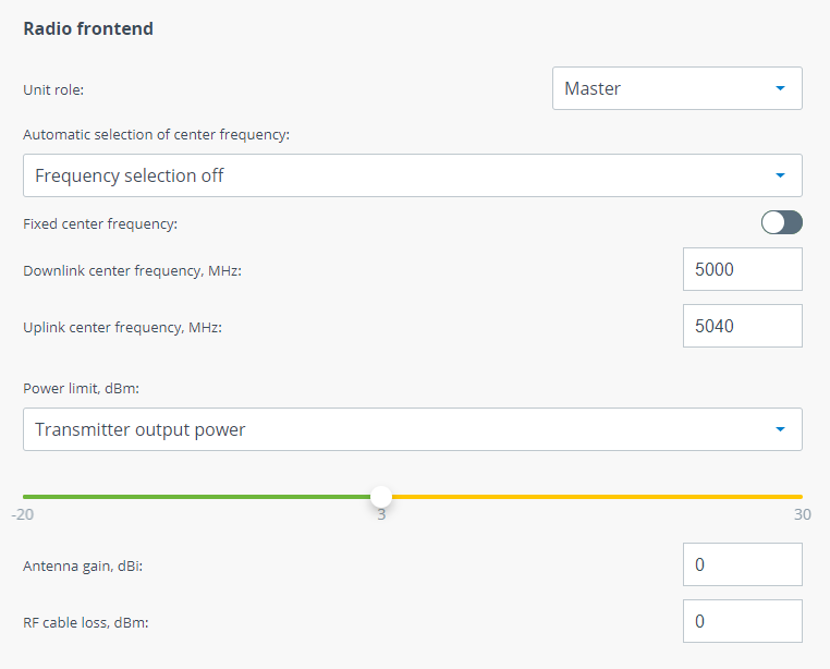
Radio frontend
| Parameter | Description |
|---|---|
| Unit role | One units must be set to Master and the other one to Slave. Please note that the following settings must be equal for "master" and "slave" unit to establish the radio link:
When a wireless link is established Slave unit will continuously inherit radio frontend parameters from Master unit excluding frequency channel grids. So, if you change some values on Master they will be set on Slave automatically. |
| Automatic selection of center frequency | There are several way to define center frequencies in Quanta 5:
|
| Independent UL/DL center frequencies | Units may transmit on diffrerent center frequencies.
|
| Power limit | This parameter limits the transmitter power, there are two modes:
Tx Power + Antenna gain + Cable loss |
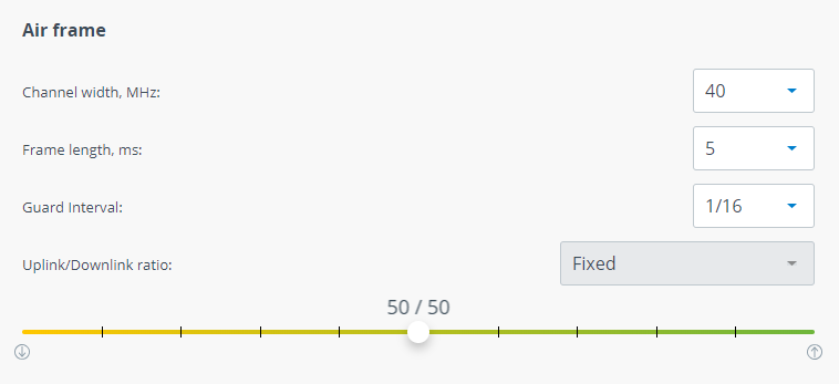
Air frame
| Parameter | Description |
|---|---|
| Channel width | Channel width, shoud be the same on both Master and Slave units. |
| Frame period | Frame period affects the following wireless link metrics:
Please note that frame period value is strongly depends on interference conditions. If larger frames will be dropped the larger payload is lost and system performance is decreased significantly. If smaller frames will be dropped the smaller payload is lost. |
| Guard interval | Guard interval is intended for intersymbol interference elimination. One of the intersymbol interference reasons is multipath propagation in which a wireless signal from a transmitter reaches the receiver via multiple paths. Guard interval affects payload size. So it should be increased only in case of significant intersymbol interference. |
| Uplink/Downlink ratio | Allows to configure quotes for uplink and downlink directions. Available values depend from:
|
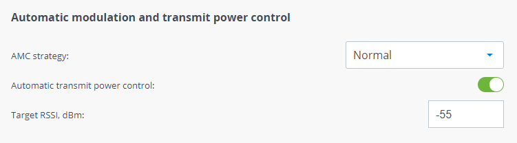
Automatic modulation and transmit power control
| Parameter | Description |
|---|---|
| AMC strategy | There are folowing AMC strategies available:
|
| Automatic transmit power control | ATPC allows to control transmitter output power automatically. Each unit has its own target RSSI level value calculated automatically. If actual RSSI level is lower then unit increases transmitter output power of the remote unit and vice versa. ATPC could not set value that may exceed the "Power limit" value.
|
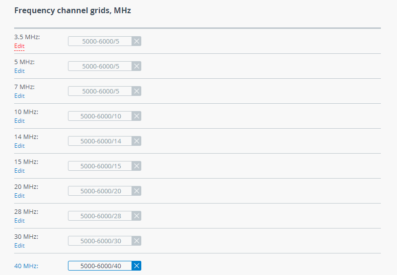
Frequency channel grids
Each available channel width is connected with appropriate channel grid. Grid is used for automatic center frequency selection function and contains a list of frequencies that may be selected. In the example below you may see that wireless unit with enabled "Automatic center frequency selection" may change center frequency to the following values (MHz): 5100, 5120, 5140, 5300, 5390, 5410.
5100-5140/20, 5300, 5390-5410/20
Each element of list may be set as follows:
- 5300 - exact value;
- 5100-5140/20, 5390-5410/20 - range of values with 20 MHz step.