This document contains sub-pages with examples:
Content
Introduction
This document describes the InfiNet devices ability to provide sustainable wireless connectivity with mobile objects in various scenarios. There is a basic project presented genarally and the features of its implementation for the mining industry, railway and water transport.
The task
Let's look at the basic scenario (Figure 1), which involves the movement of one or more objects throughout the enterprise area along a given path between points A and B. The network control center is located at a distance from the area there the moving object can be located.
The project goal is to organize a reliable wireless connectivity between the control center and mobile objects to provide various information services, such as telemetry data gathering, video surveillance, telephony, etc.
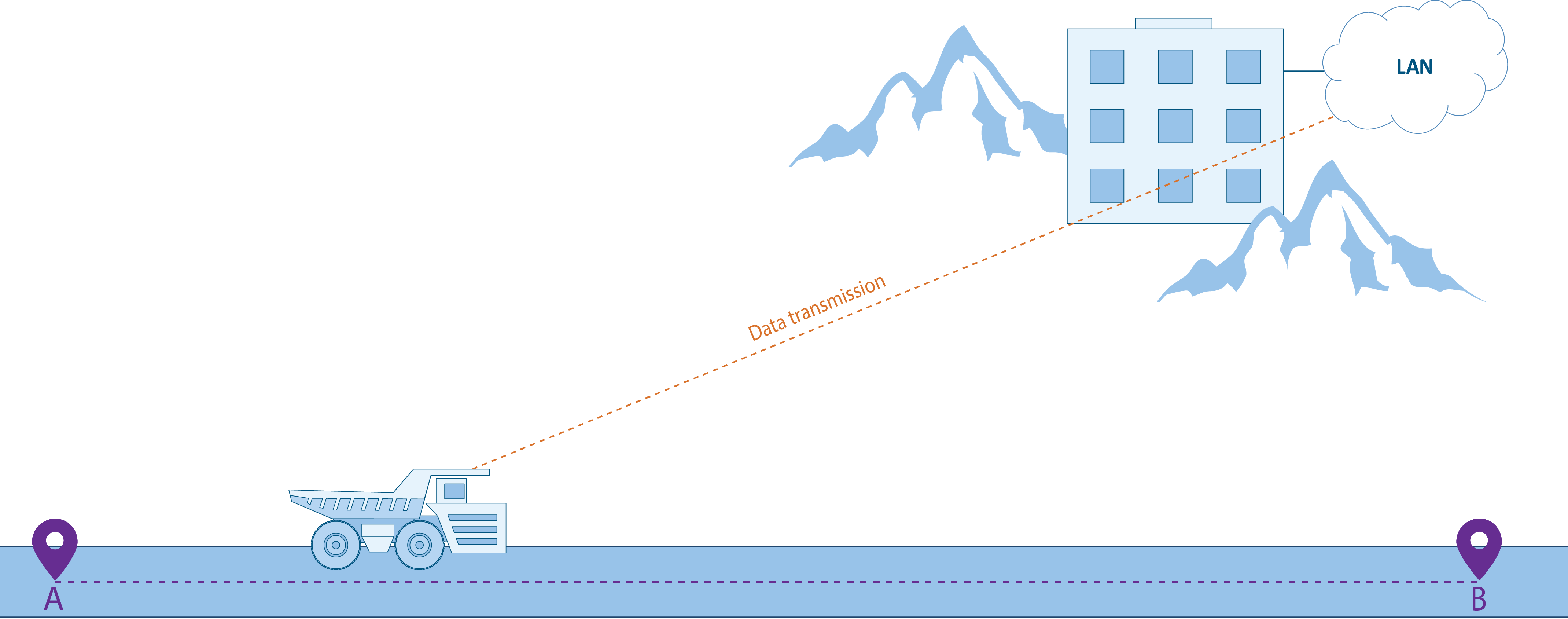
Figure 1 - Basic scenario for connectivity with mobile objects
Two categories of tasks must be solved to achieve this goal:
- Network establishment:
- A backbone radio network creation. The coverage of the backbone radio network should correspond to the object movement area.
- An aggregation node creation. The aggregation node is designed to join the backbone radio network devices and is a gateway between the radio network and the enterprise network.
- To establish a backbone link between the aggregation unit and the control center.
- Fault tolerance and roaming providing:
- Ensuring the link fault tolerance at the access level.
- Providing seamless subscriber roaming within the backbone radio network.
- Ensuring fault tolerance of the main link between the aggregation unit and the control center.
- Ensure the possibility of QoS policy implementation.
The solution
Network establishment
The solution of the network establishing problems described above is shown in Figure 2. The solution can be divided into four components:
- An enterprise network.
- An aggregation node.
- A backbone radio network.
- Object movement area.
The backbone radio network consists of several base stations (BS) joined by a wired infrastructure. Each BS can consist of one or several sectors, the combination of their antenna patterns forms the radio network coverage area. As CPEs and BS sectors, the InfiMAN 2x2 family devices can be used. Keep in mind that wireless links as well as combined infrastructure can be used to join several BSs.
The base stations are joined by the aggregation node where the InfiMUX switch is installed. As shown below, the InfiMUX simplifies the configuration of InfiNet devices by adding all BSs into a single MINT area.
A backbone link is established between the aggregation node and the network control center. The choice of channel-forming devices is determined by the transmitted traffic capacity (see Performance of the InfiNet Wireless devices) the following throughput values can be achieved:
- InfiLINK 2x2 family devices: upto 280 Mbps.
- InfiLINK XG family devices: upto 500 Mbps.
- InfiLINK XG 1000 family devices: upto 1000 Mbps.
One subscriber station (CPE) is installed on each mobile object, the configuration contains radio profiles for each BS sector. The operation principle is that CPE can switch the connections while moving between BS. Since the BS sectors provide coverage for the entire area in which the CPE can be located, the CPE is always in the coverage area of at least one BS. As soon as the radio parameters of the current connection deteriorate, the CPE breaks the radio link and connect to another sector. So, while the object moving from point A to point B (Figure 2) the CPE is connecting one by one to the sectors BS1, BS2, BS3 and BS4.
Keep in mind that CPE cannot be simultaneously connected to two BS, because the device has one radio module, so CPE switching between the BSs is accompanied by a short-term connectivity break. Several CPEs can be simultaneously connected to one BS sector.
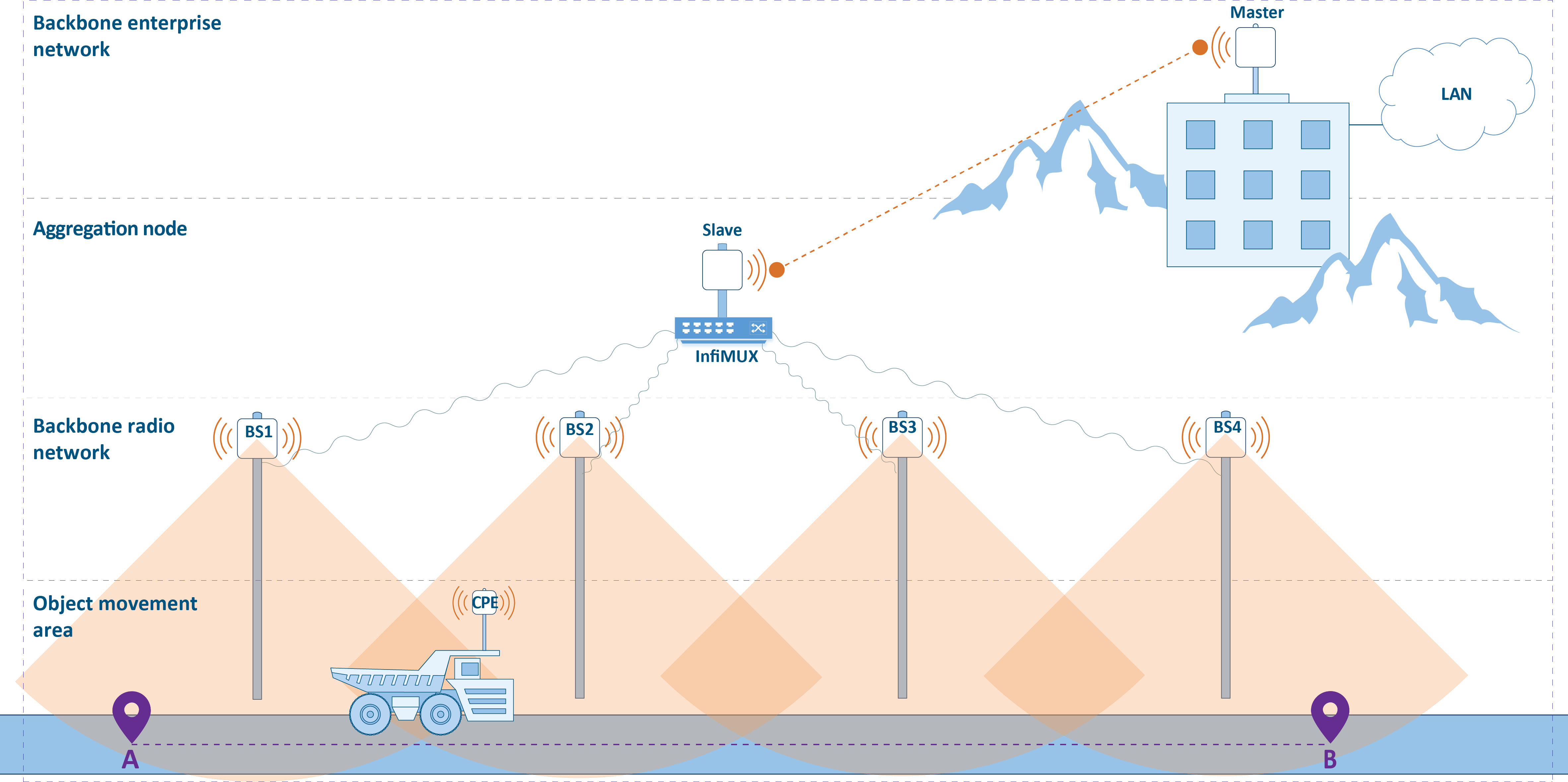
Figure 2 - Areas distribution
Fault tolerance and roaming
In addition to the infrastructure described earlier there is extended list of tasks, which makes the solution fault-tolerant and more efficient:
- The link fault tolerance at the access level is ensured by overlapping sectors radiation patterns on the backbone radio network designing stage. So, if there is an overlap with neighboring sectors more than 50%, one the sector failure will not affect the coverage area of the radio network. Radio frequency planning requires a complex approach and is discussed more detaily in the following sections.
- As noted, roaming in the proposed solution is not seamless, because CPE switching between different BS is accompanied by a connectivity break. A seamless roaming requires an installation of a second CPE on each moving object. Such a solution is detaily described below.
- InfiNet devices can be used in various scenarios of point-to-point links reservation and aggregation. For example, the backbone link can be reserved using proprietary failover technology which requires an installation of a second wireless devices set. Failover allows automatic reservation of the backbone link using only one frequency channel. Options for organizing link reservations are presented in the Link aggregation, balancing and redundancy document.
An implementation of a QoS policy does not require the additional devices installation and is solved by the wireless devices and InfiMUX configuration:
- The telemetry gathering service, telephony and the remote control are sensitive to delay and jitter, so they require careful configuration of traffic distribution rules by classes. Low jitter for sensitive services can be achieved by using software with TDMA technology support on InfiMAN 2x2 devices. A comparative analysis of Polling and TDMA multiple access technologies is provided in the TDMA and Polling: Application features document.
- The video surveillance service, in addition to the delay requirements, requires the throughput in the uplink from CPE to BS. The InfiMAN 2x2 devices family supports the time division multiple access method (TDMA), which allows an administrator flexibly allocate available throughput between upstream and downstream channels.
- Using a single infrastructure to provide a range of different services requires flexible allocation of available throughput between them..
Radio planning
Each the considered solution implementation is unique and requires careful preliminary planning. It is a very important stage, saving resources at the design stage can greatly increase operating costs. Within this document the radio frequency planning issues and devices placement will be reviewed.
RF planning
Frequency planning is a complex creative process that defines:
- Installation coordinates.
- Suspension height, azimuth and antenna elevation.
- Devices partnumbers.
- Frequency channels and transmission power.
The result of frequency planning is a device allocation map with basic radio settings. A convenient tool for radio planning and potential performance assessment depending on the radio parameters is InfiPLANNER.
The frequency channel selection is determined by the following factors:
- Regulatory restrictions: RF regulation is determined at the legislative level. Usually, a frequency range is allocated that is allowed for free use with certain restrictions (radiated power, antenna suspension height, etc.), and a frequency range for which the permission must be obtained.
- Radio module capabilities: the wireless device radio module supports a limited set of emitted frequencies, this should be taken into account at the designing stage.
- Physical features of the electromagnetic waves propagation: propagation distance, the effect of precipitation and interaction with obstacles are determined by the electromagnetic wave frequency, which must be keep in mind during preliminary calculations. The radio waves propagation effects are detaily described in the Wireless Networking Fundamentals online course.
- The interference level: the operation of third-party wireless devices has a significant impact on system performance, take it into account when designing. The interference level is affected by the radiation power and the frequency channels used on third-party devices operating in the area. In addition to interference from third-party devices, the neighboring sectors can have influence on each other. Reducing interference from own devices can be achieved by using different frequency channels. Recommendations for frequency diversity are given in the TDMA and Polling: Application features document. Particular attention should be paid to the frequency channels selection in projects with multisectoral configurations in order to minimize the influence of the BS sectors on each other.
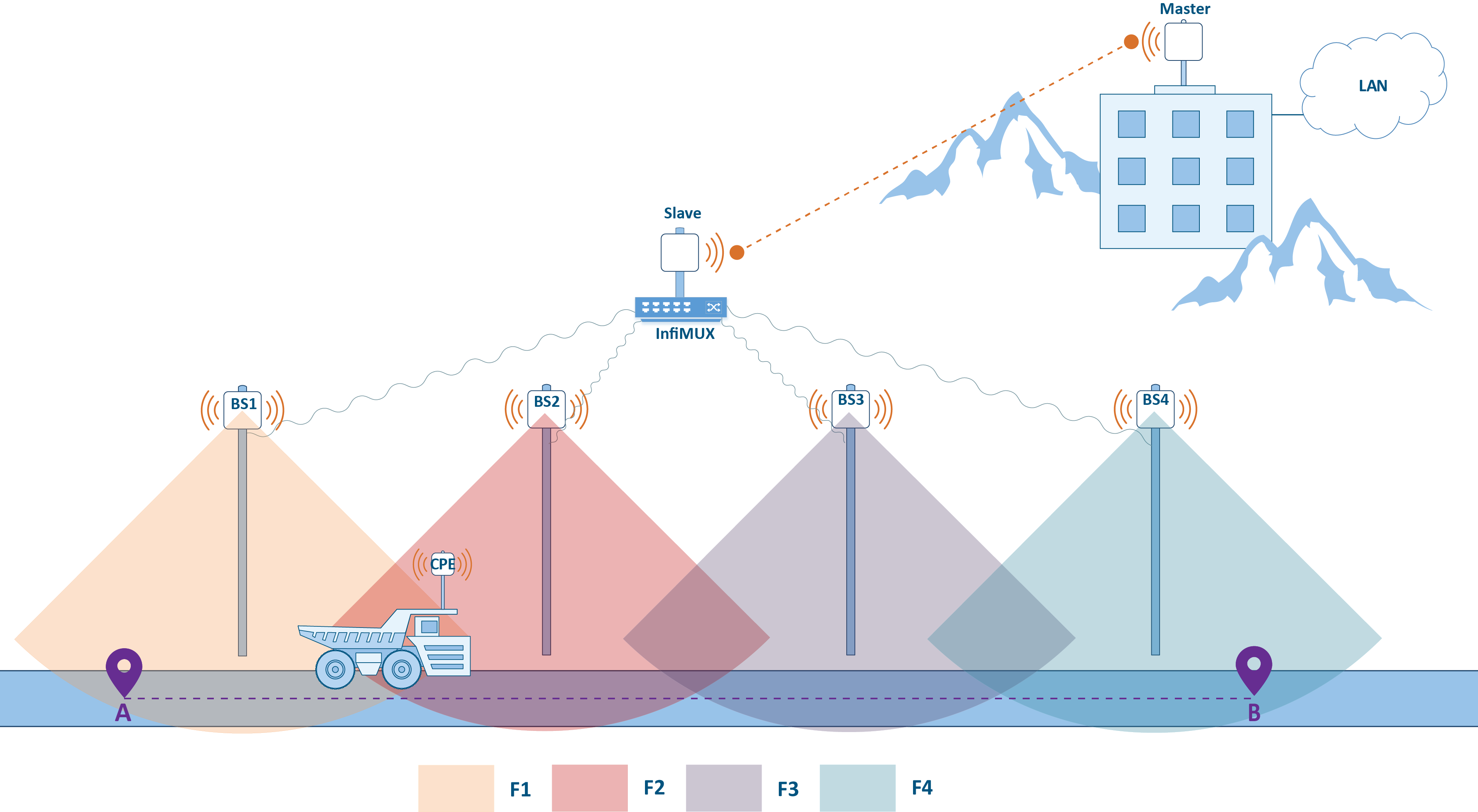
The frequency distribution examples are presented below. Figure 3a illustrates a scheme there each BS sector has it's own frequency channel. This approach requires the allocation of 4 frequency channels.
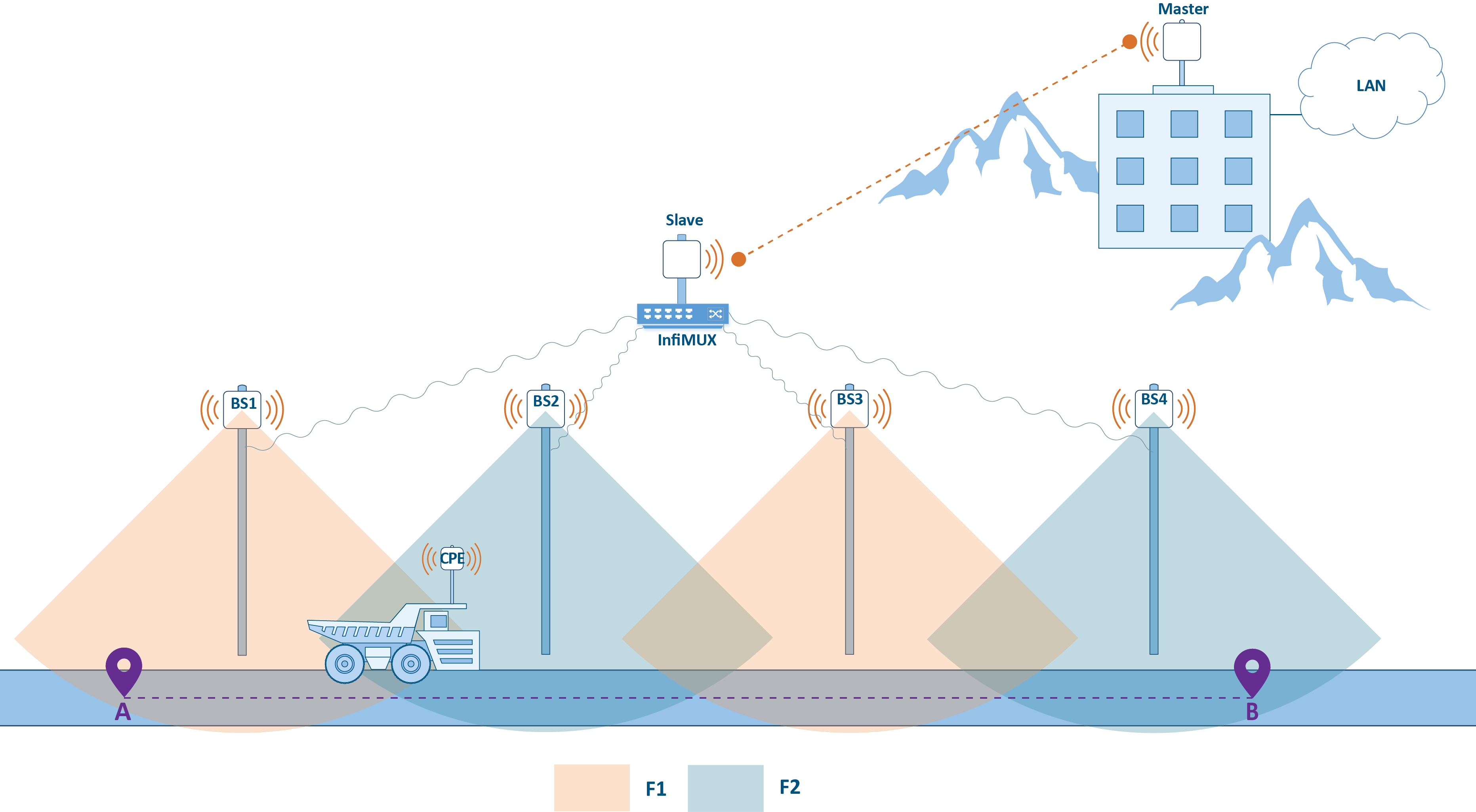
Let's look at the optimized scheme (Figure 3b).Since the sectors position is chosen in such a way that the radiation patterns of BS1 and BS3, BS2 and BS4 do not intersect in pairs, they will not interfere with each other. This will optimize the frequency resource used, reducing the number of frequency channels from 4 to 2.
a)
b)
Figure 3 - The allocation of frequency channels between BS: a - using four channels, b - using two channels
Device allocation
The device position in space determines the actual quality indicators of the wireless link. The position of the device is determined by:
- Installation coordinates.
- Azimuth and antenna elevation.
- Suspension height.
In projects with mobile objects, the antennas directional properties should be taken into account. If the BSs are static and the radio coverage area is constant, then the CPEs antenna radiation pattern can greatly affect the link quality. InfiNet's product portfolio includes devices with integrated antennas and the ability to connect external antennas, the device selection is determined by the project specifics.
The route profile must be evaluated along the entire object trajectory. This will allow to find potential "dead zones" there will be no connection with the object and change the location of the BS if necessary. In addition, perform a survey on enterprise the territory, because the InfiPLANNER link planning tool does not take into account the effects of obstacles such as trees, buildings, etc.
The InfiNet product portfolio includes a wide range of accessories, including mounting kits that allow to install devices in various conditions with the possibility of flexible alignment, and the CAB-RV1 alignment tool which allows to perform preliminary device diagnostics.
MINT protocol
Ethernet link layer protocol was developed for wired networks and does not take into account the specifics of the wireless environment. Wireless device manufacturers can use standard wireless protocols, such as Wi-Fi, or use their own developments. InfiNet Wireless company is developing a proprietary data transfer protocol called MINT designed for data exchange in a wireless environment.
MINT (Mesh Interconnection Network Technolohy) - InfiNet's proprietary technology used in InfiLINK 2x2 and InfiMAN 2x2 family devices, provides data transfer between devices via wireless and wired links.
MINT area
One of the MINT protocol main concepts is the MINT area. A MINT area consist of many neighboring devices, data exchange between them is carried out using MINT frames (see "MINT protocol" lesson of the InfiLINK 2x2 and InfiMAN 2x2: Switching online course).
Let's look at the solution described above applying MINT areas concept (see Figure 4). A radio link is installed between the Master and Slave devices, they form the MINT 5 area. Each of the BS1, BS2, BS3, and BS4 sectors is potentially ready to establish a radio link with CPE installed on the mobile object, forms a separate MINT area with the corresponding identifier.
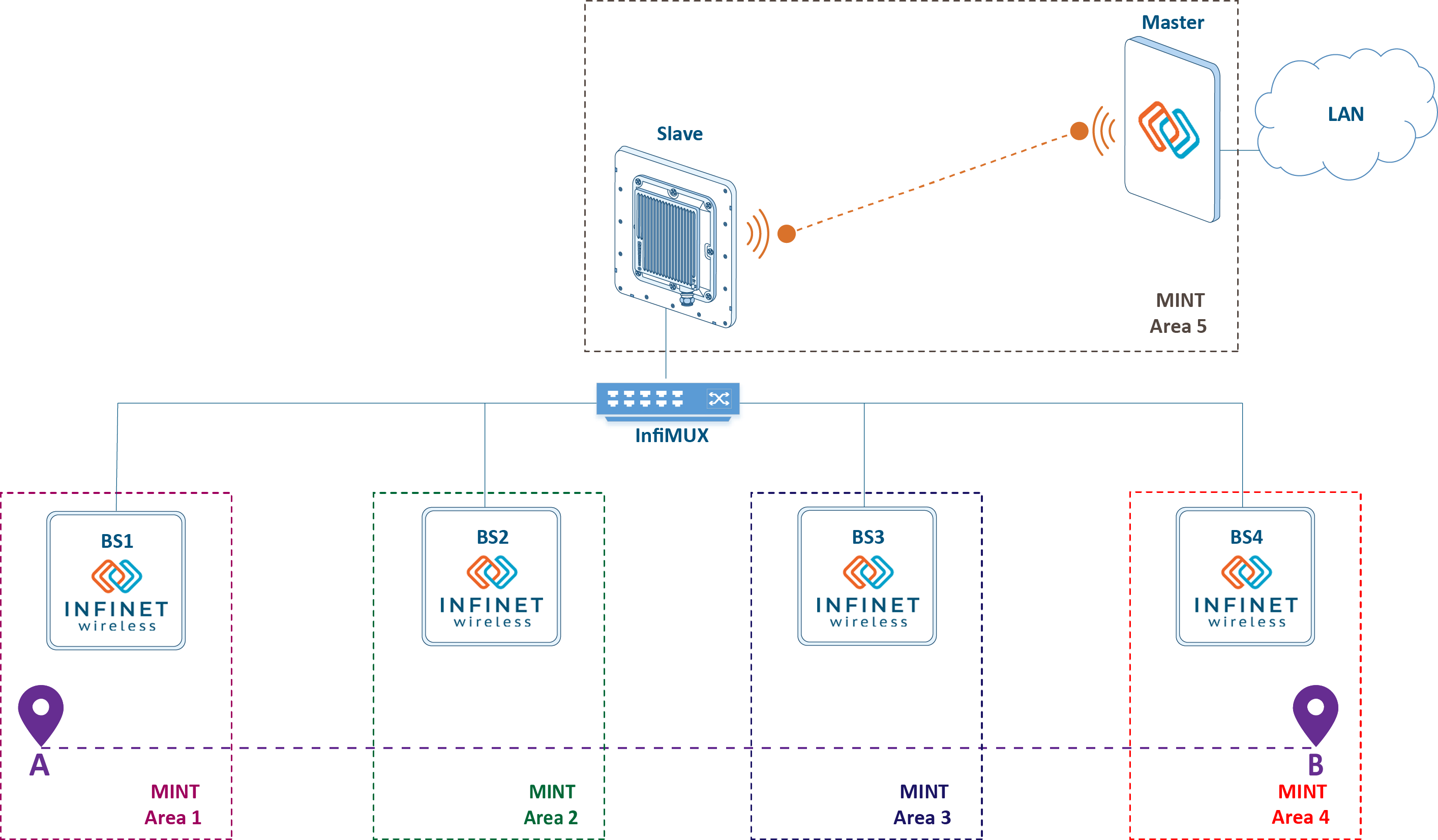
Figure 4 - Many MINT areas in the scheme with mobile objects
Note that the MINT protocol is intended for data exchange within the MINT area. Data outside the MINT area can be transmitted using other channel protocols, such as Ethernet, i.e. CPE and each of the BS sectors is the gateway between MINT and Ethernet. In the our scheme, data is exchanged between a mobile object and a control center, i.e. the frame will go through several Ethernet segments and MINT areas in the forward and backward directions. Thus, switch groups configuration on each device is a prerequisite for data transfer:
switch group 1 add eth0 rf5.0
switch group 1 start
switch start
In addition to Ethernet frames encapsulation during transmission through the MINT area, the MINT protocol performs an exchange of service messages to fill in the frame redirection table. The frame redirection table allows to select the frame transmission route (see video 5) through the MINT area in accordance with the radio parameters and the link load. This mechanism guarantees the selection of the route with optimal radio parameters and prevents loops.
Video 1 - An example of route selection between nodes J and F in MINT
If necessary, you can influence the path selection algorithm by setting the link metrics value manually. This can be done by summing the calculated and additional costs or fixing a certain value (switching in InfiNet devices is detaily described in the online course InfiLINK 2x2 and InfiMAN 2x2: Switching)
mint rf5.0 -extracost 1000
mint rf5.0 -fixedcost 1000
Data transfer and QoS configuration on each wireless devices is a time-consuming task that can be simplified by expanding the MINT area. Schemes intended to reduce the wireless devices configuration by combining them into a single MINT area are shown below.
Joining sectors into one MINT area using InfiMUX
The main disadvantage of the solution above is a necessary switch groups configuration on all wireless devices. Since the switch group is a gateway between MINT and Ethernet, it is possible to combine all the BSs of the radio network into a single MINT area by assigning the gateway function to the InfiMUX switch (see Figure 5). In this case, the switch group is need to be configured only on InfiMUX. Joining devices into a single MINT area and the advantages of such a scheme are described in the InfiLINK 2x2 and InfiMAN 2x2: Switching online course.
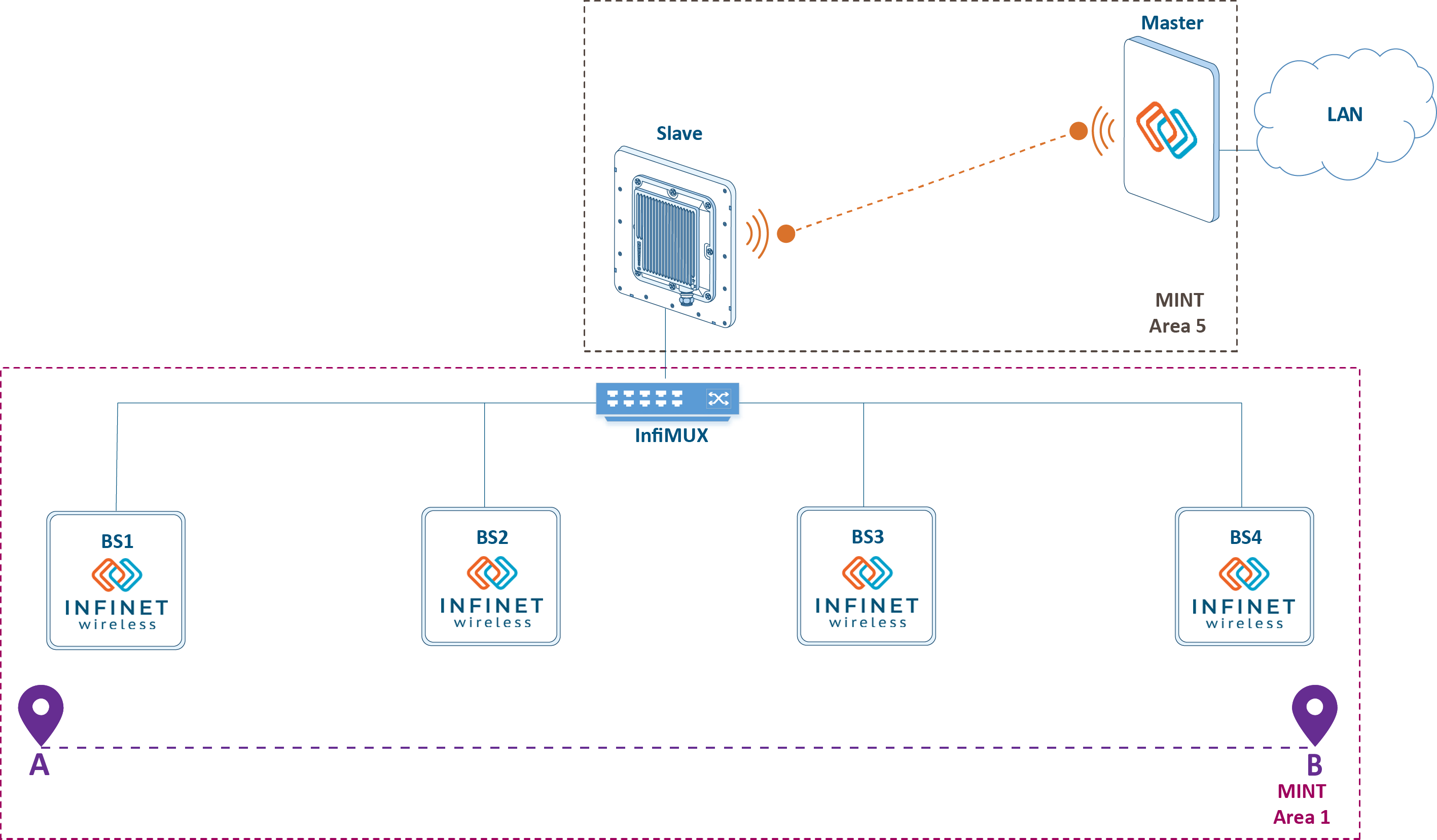
Figure 5 - Joining the backbone radio network into a single MINT area
Using MINT protocol in a wired infrastructure is possible with PRF (pseudo radio) interface. It is a virtual interface that has a wired interface as a parent and encapsulates MINT frames in Ethernet frames. Configuration via CLI:
Create a PRF interface on a wireless device or InfiMUX:
Create PRF interfaceifc prf0 mtu 1500 up prf 0 parent eth0 hwmtu 1514 mint prf0 start
Join RF and PRF interfaces on the wureless device:
RF and PRF interfaces joiningmint join rf5.0 prf0
Join two PRF interfaces on InfiMUX:
Two PRF interfaces joiningmint join prf0 prf1
The advantages of such solution is the simplification of the QoS configuration, as traffic processing rules for different service classes are configured only on InfiMUX.
Joining sectors and the backbone link in one MINT area
The disadvantage of the scheme with backbone radio network devices joining in a single MINT area is the quality of service policy complication: the used traffic classification rules must be duplicated on InfiMUX and on the Master and Slave devices. If these rules are not duplicated, the effect of QoS policy implementation can be significantly reduced.
One of the solutions is to combine the channel-forming devices of the link into a single area with all other devices (see Figure 6). This solution is realizable only when using InfiLINK 2x2 family devices on the backbone link. In this case, the unified traffic classification rules configured on the Master device will be valid in the entire MINT area. In addition, the gateway functions between MINT and Ethernet can be transferred to the Master device, any switch can be used instead of InfiMUX. Areas joining is carried out similar way as the above configuration.
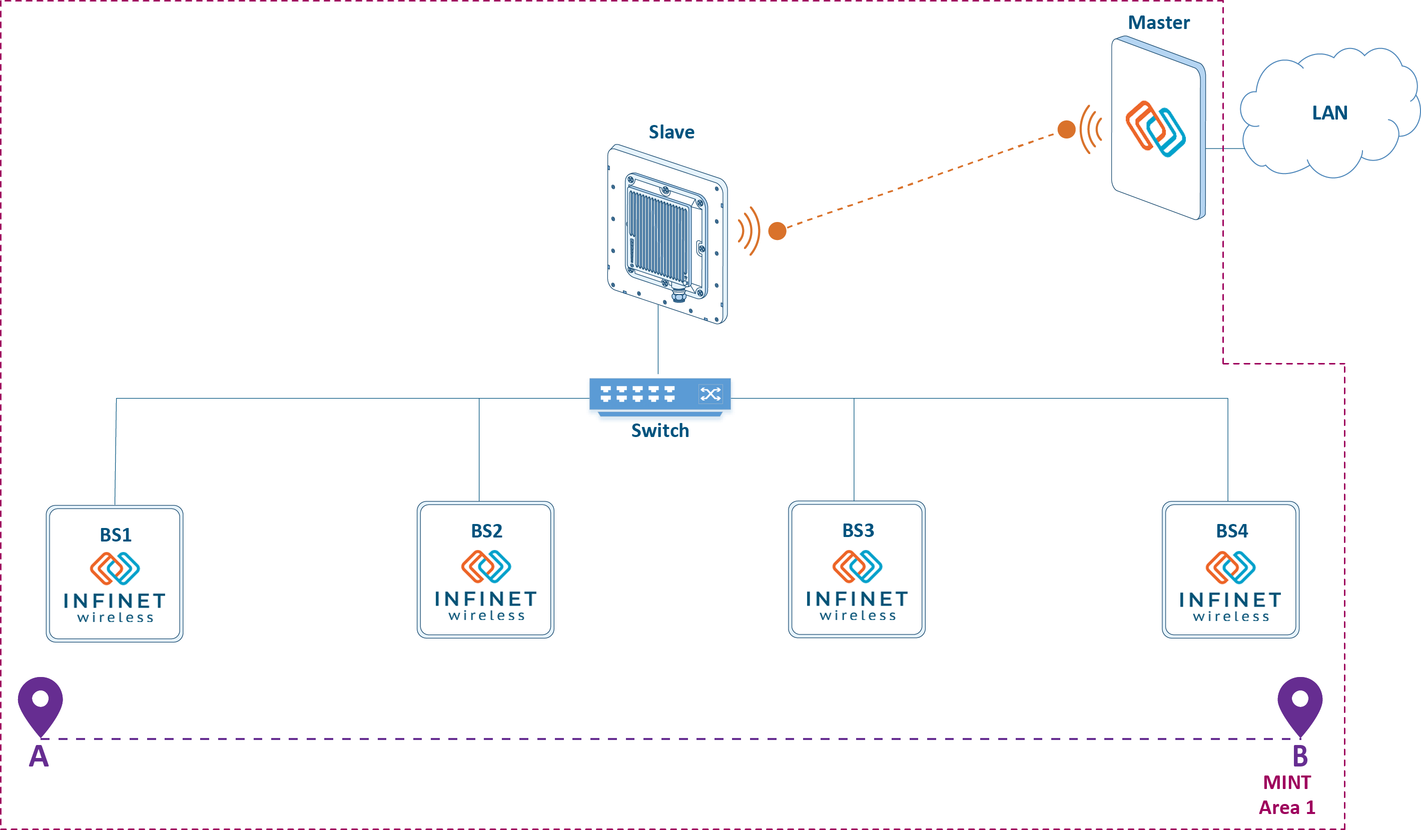
Figure 6 - Joining all wireless devices in a single MINT area
Roaming
The movement of the mobile object with CPE installed, within the backbone radio network is accompanied by a transition from the coverage area of one BS sector to another sector coverage area of same or another BS. The CPE transition process between BS sectors is called roaming. Roaming is accompanied with radio link brake with the first sector and the connection establishment with the second sector.
Let's look at the roaming mechanism (see video 2):#min_max
- There is a radio link between CPE and BS1.
- The vehicle moves and the radio link between CPE and BS1 breaks. The reason is the inability to maintain communication due to insufficient signal energy. As it is shown below, the breakage initiator of the radio link can be both CPE and the corresponding sector BS1.
- The CPE is trying to reconnect to BS1. If successful, the algorithm returns to step 1; if not - to step 4.
- The CPE searches for devices to establish the radio connection.
- CPE finds out BS2 and tries to establish a connection with it.
- CPE establishes a radio link with BS2.
Video 2 - Roaming mechanism
Radio link establishing
A radio link can be established between two devices if the following requirements are met:
- At least one device has a Master role. Possible connections: Master-Master, Master-Slave. The solution architecture suppose configuration of BS sectors as Masters, and CPEs as slaves.
- A radio profile has been created in CPE configuration, corresponding to the radio settings on the BS.
- Signal parameters (RSSI, SNR, etc.) allow data exchange at least at the minimal modulation.
Radio profiles
On Master devices, only one set of radio parameters can be configured, which will be used to establish links. On Slave devices, several radio profiles can be created, or one with the ability to automatically select a frequency. Configuration via CLI:
Configure radio parameters on the Master device:
Frequency configuration on the Masterrf rf5.0 band 20 rf rf5.0 mimo greenfield rf rf5.0 freq 5510 bitr 130000 sid 10101010 burst rf rf5.0 txpwr auto pwrctl distance auto
Create a radio profile on the Slave device with a fixed frequency value:
Radio profile with fixed frequencymint rf5.0 prof 1 -band 20 -freq 5510 -sid 10101010 \ -nodeid 60755 -type slave \ -autobitr -mimo greenfield
Create a radio profile on the Slave device with automatic frequency selection (if a profile with a fixed frequency value is used, the command below will not be executed):
Radio profile with automatic frequency selectionmint rf5.0 prof 1 -band 20 -freq auto -sid 10101010 \ -nodeid 60755 -type slave \ -autobitr -mimo greenfield
When Slave device tries to establish a connection, it cyclicaly look over the radio profiles added to its configuration. Как только один из профилей подходит для установки радиоканала, создаётся связь с ведущим устройством и перебор профилей прекращается. В случае, если в конфигурации создан профиль с автоматическим выбором частоты, ведомое устройство пытается установить соединение с ведущим, перебирая частоты, поддерживаемые радиомодулем. Список частот, перебираемый ведомым устройством может быть ограничен конфигурацией пользовательской частотной сетки.
Пример настройки пользовательской сетки частот через CLI (для интерфейса rf5.0 указывается диапазон частот от 5000 МГц до 5100 МГц с шагом 10 МГц, которые могут быть использованы в качестве центральной частоты канала при ширине канала 20 МГц):
rf rf5.0 grid 20 5000-5100/10
Очевидно, что установка связи может оказаться длительной операцией при использовании режима автоматического выбора частоты на ведомом устройстве из-за широкого диапазона частот, поддерживаемых радиомодулем. В рассматриваемых сценариях с роумингом это неприемлемо, поэтому рекомендуется в конфигурации АС создавать отдельные радиопрофили для каждого из секторов БС опорной радиосети.
Динамический выбор частоты
Устройства с ролью "ведущий" по аналогии с "ведомым" поддерживают режим динамического выбора частот (DFS). Устройства с поддержкой DFS перед выбором частоты выполняют сканирование доступных частотных каналов, оценивают уровень интерференции и наличие радаров. Среди частотных каналов, свободных от радаров, выбирается канал с минимальным уровнем интерференции, который устанавливается в качестве рабочего.
DFS является стандартной технологией для беспроводных устройств, однако её недостаток состоит в том, что оценка радиообстановки выполняется только при включении и не актуализируется в процессе работы. Использование дополнительного радиомодуля на некоторых моделях устройств Инфинет позволяет реализовать фирменную технологию Instant DFS. Дополнительный радиомодуль постоянно сканирует эфир, выполняя переход между частотными каналами в соответствии с уровнем интерференции. Технологии DFS, Radar detection и Instant DFS подробно описаны в документе Динамический выбор частоты.
Настройка DFS через CLI:
Активируйте DFS на устройстве с ролью "ведущий":
Активация DFSdfs rf5.0 dfsonly dfs rf5.0 freq auto
Активируйте DFS и Radar detection на устройстве с ролью "ведущий":
Активация DFS и Radar detectiondfs rf5.0 dfsradar dfs rf5.0 freq auto
Активируйте поддержку iDFS на устройствах с ролью "ведущий" и "ведомый":
Активация iDFSmint rf5.0 -idfs
Частотный роуминг
Под частотным роумингом в этом документе понимается изменение рабочей частоты установленного радиоканала, т.е. смена рабочей частоты выполняется на обоих устройствах.
Работа механизма частотного роуминга тесно сопряжёна с функцией Instant DFS, поскольку, при обнаружении частотных каналов с меньшим уровнем интерференции, чем на текущем, сектор БС в режиме PtMP или ведущее устройство в режиме PtP должны выполнить смену рабочей частоты. При этом подключенные к ним устройства, также должны выполнить смену частотного канала. Поведение устройств при частотном роуминге определяется значением параметра "roaming":
- leader: устройство определяет новый частотный канал и рассылает служебные сообщения другим устройствам для смены рабочей частоты. Целесообразно данную функцию назначить на устройство с активированной функцией DFS/iDFS.
- enable: устройство, получив команду на смену рабочей частоты от "leader", выполняет переход на новый частотный канал.
- disable: устройство, получив команду на смену рабочей частоты от "leader", игнорирует её.
В рассматриваемом решении не используется технология DFS, однако в проектах, где необходимо использование DFS/iDFS, целесообразно настроить секторы БС как "roaming leader", а АС - как "roaming enable".
Настройка через CLI:
Активируйте роуминг на устройстве с ролью "ведущий":
Конфигурация сектора БСmint rf5.0 roaming leader
Активируйте роуминг на устройстве с ролью "ведомый":
Конфигурация АСmint rf5.0 roaming enable
Перезапустите интерфейс rf5.0 на устройствах с ролями "ведущий" и "ведомый":
Конфигурация АС и БСmint rf5.0 restart
Важно отметить, что ведомое устройство с "roaming enable", получив команду на смену рабочей частоты от "roaming leader" выполнит переход в другой частотный канал даже в том случае, если в конфигурации ведомого устройства не будет соответствующего радиопрофиля. При этом, после перезагрузки, ведомое устройство не сможет установить радиоканал, т.к. будет руководствоваться набором радиопрофилей, добавленных в конфигурацию.
Функция MultiBS
Главным недостатком механизма роуминга является то, что АС, после разрыва канала связи с БС1, пытается восстановить это соединение и, только после нескольких неудачных попыток, выполняет поиск других БС для установления радиоканала. Устройства Инфинет поддерживают фирменную функцию MultiBS, позволяющую ускорить этот процесс.
Механизм роуминга с функцией MultiBS представлен ниже (см. видеоролик 3):
- Между АС и БС1 установлен радиоканал.
- Автомобиль перемещается и параметры радиоканала между АС и БС1 ухудшаются. АС разрывает канал связи с БС1. Несмотря на то, что радиоканал между АС и БС1 может быть использован для передачи данных, АС замечает отрицательный тренд и превентивно разрывает канал связи.
- АС выполняет поиск устройств, с которыми можно установить радиоканал.
- АС находит один из секторов БС2 и пытается установить канал связи с этим устройством.
- АС устанавливает радиоканал с одним из секторов БС2.
Видеоролик 3 - Механизм роуминга с функцией MultiBS
Активация функции MultiBS выполняется следующим образом:
mint rf5.0 roaming enable multiBS
Функция Global
Рассмотрим сценарий, в котором была повреждена кабельная трасса между InfiMUX и инжектором питания БС1 (см. рисунок 7), т.е. питание к БС1 подведено и устройство готово устанавливать радиосоединения, но передача данных в центр управления невозможна.
Автомобиль с установленным комплектом АС начинает движение по траектории из точки А в точку B. Находясь в зоне действия БС1, АС устанавливает с ней радиоканал. Поскольку кабельная трасса повреждена, то данные между подвижным объектом и центром управления не передаются. Двигаясь вдоль траектории, подвижный объект попадает в область, когда существует возможность подключиться к БС2, но параметры установленного канала связи с БС1 удовлетворительны и АС не выполняет роуминг между БС. Без настроенной функции MultiBS, АС будет поддерживать связь с сектором БС1 до момента выхода из зоны радиопокрытия сектора БС1.
Фирменная функция Global позволяет избежать подобной ситуации. В случае, если в конфигурации АС активирована функция Global, то АС будет устанавливать радиоканал только с устройствами, на которых тоже активна функция Global. Кроме того, устройства в одной области MINT могут выполнять проксирующую функцию по отношению к устройствам с активированной функцией Global. Таким образом, если в конфигурации InfiMUX и АС активировать функцию Global, то все БС в момент установления радиоканала будут сообщать АС о том, что через них доступен InfiMUX, у которого активирована функция Global. Если между БС1 и InfiMUX повреждена кабельная трасса, то БС1 не будет сообщать АС о доступности InfiMUX, т.е. АС не установит радиоканал с БС1.
Использование функции Global позволяет повысить отказоустойчивость опорной радиосети, однако её использование будет иметь эффект только при соответствующем радиочастотном планировании - области покрытия секторов должны быть выполнены с перекрытием.
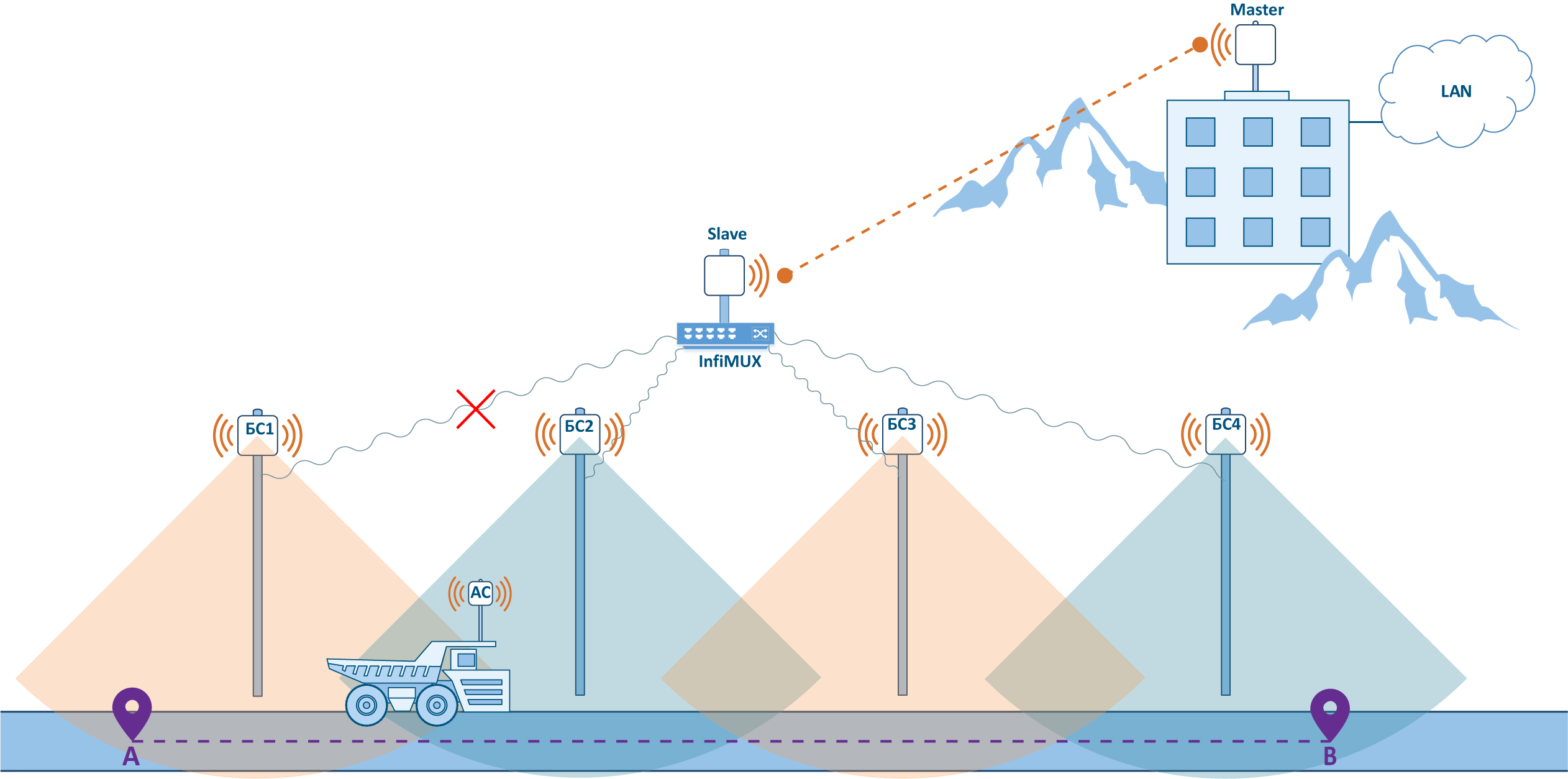
Рисунок 7 - Использование функции Global
Настройка устройств через CLI:
Активируйте функцию Global на АС:
Активация функции Global на АСmint rf5.0 roaming enable global
Активируйте функцию Global на InfiMUX:
Активация функции Global на InfiMUXmint prf0 roaming enable global
Параметры управления процессом установления радиоканала
Одним из механизмов, определяющим момент разрыва связи с одним сектором и установления связи с другим сектором, является оценка пороговых значений SNR. В конфигурации беспроводных устройств выделяют два пороговых значения:
- hiamp: минимальное значение SNR, требуемое для установления радиоканала между двумя устройствами.
- loamp: минимальное значение SNR, при котором радиоканал между устройствами не будет разорван.
Таким образом, настройка пороговых значений на БС или АС является одним из механизмов по управлению процессом роуминга АС.
Конфигурация уровня SNR для установления радиоканала на беспроводных устройствах выполняется с помощью следующих команд:
mint rf5.0 -hiamp 2
mint rf5.0 -loamp 0
Режимы fixed/mobile/nomadic
Одним из факторов, влияющих на параметры канала связи с подвижным объектом, является степень актуальности таблицы перенаправления кадров MINT. Поскольку речь идёт о таблице перенаправления MINT, то данная настройка может быть применена только на устройствах семейств InfiLINK 2x2 и InfiMAN 2x2. В конфигурации устройств можно установить интервал обновления записей таблицы перенаправления MINT, выбрав одно из трёх значений параметра "mode":
- fixed: обновление таблицы перенаправления выполняется с интервалом 3 секунды. Данный режим предназначен для организации каналов связи со статичными объектами.
- nomadic: обновление таблицы перенаправления выполняется с интервалом 1,5 секунды. Данный режим предназначен для организации каналов связи с подвижными объектами малой скорости.
- mobile: обновление таблицы перенаправления выполняется с интервалом 1 секунда. Данный режим предназначен для организации каналов связи с подвижными объектами.
АС с активированной функцией MultiBS, как показано выше, выполняет сравнение текущих показателей радиоканала с максимально достигнутыми. Возможен сценарий, в котором параметры радиоканала резко ухудшатся из-за кратковременного влияния помехи и так же резко восстановятся. АС разорвёт связь с БС в соответствии с алгоритмом работы функции MultiBS, несмотря на то, что ухудшение параметров радиоканала носило кратковременный характер. Выбор значения параметра "mode" влияет на анализ радиопараметров при активированной функции MultiBS, задавая временной интервал оценки. Таким образом устройство со значением параметра "mode fixed" выполняет оценку радиопараметров на интервале трёх секунд и более устойчиво к разрыву радиоканала в условиях кратковременных помех, чем устройство со значением "mode mobile".
Установка значения параметра mode в конфигурации устройства может быть выполнена следующим образом:
Установите режим fixed на устройствах с ролью "ведущий" и "ведомый":
Конфигурация режима fixedmint rf5.0 -mode fixed
Установите режим nomadic на устройствах с ролью "ведущий" и "ведомый":
Конфигурация режима nomadicmint rf5.0 -mode nomadic
Установите режим mobile на устройствах с ролью "ведущий" и "ведомый":
Конфигурация режима mobilemint rf5.0 -mode mobile
Использование двух абонентских устройств на объекте
Активация функции MultiBS, как показано выше, ускоряет роуминг АС между БС, однако, в любом случае, роуминг сопровождается кратковременным перерывом связи. Избежать перерыва связи позволяет использование двух АС на подвижном объекте, объединённых с помощью InfiMUX. В этом случае каждая из АС будет независимо устанавливать радиоканал с БС, а InfiMUX будет принимать решение по выбору канала связи для пересылки данных.
Поясним алгоритм роуминга в схеме с двумя АС (см. рисунок 8):
- АС1 и АС2 установили радиоканал с БС1. При этом не возникает петли, т.к. все радиоустройства объединены в одну область MINT и устройства используют таблицу перенаправления кадров, учитывающую параметр стоимости.
- Автомобиль движется, АС2 разрывает канал связи с БС1. АС1 сохраняет связь с БС1. Перерыва сервиса не наблюдается, т.к. для обмена данными между автомобилем и центром управления осуществляется через канал АС1-БС1.
- АС2 начинает поиск БС для установления радиоканала. АС1 сохраняет канал связи с БС1.
- АС2 устанавливает связь с БС2. АС1 сохраняет связь с БС1. При передаче данных InfiMUX использует один из двух каналов связи АС1-БС1 и АС2-БС2, с меньшей метрикой.
- Автомобиль движется и АС1 разрывает связь с БС1. АС2 сохраняет связь с БС2. Передача данных будет выполнена через канал АС2-БС2, перерыва сервиса не наблюдается.
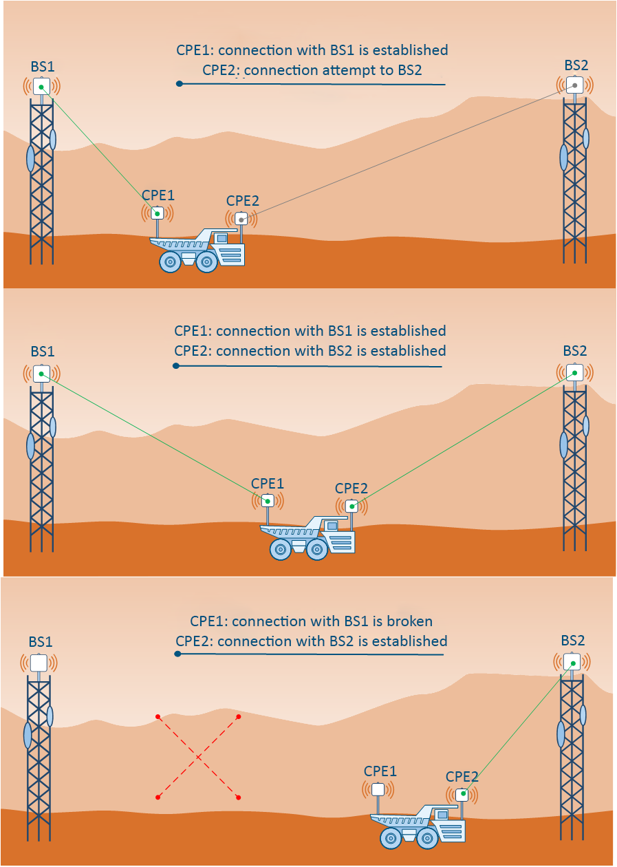
Рисунок 8 - Роуминг в схеме с двумя АС на подвижном объекте
Настройка устройств заключается в том, что на устройствах АС1 и АС2 должны быть созданы PRF-интерфейсы в сторону InfiMUX, а на InfiMUX - PRF-интерфейсы в сторону беспроводных устройств. Кроме того, настройка групп коммутации должна быть перенесена из конфигурации АС в конфигурации InfiMUX.
Следует иметь в виду, что после любых изменений в конфигурации устройств, выполненных из командной строки, следует сохранить обновлённые настройки. Команда сохранения конфигурации
config save
Дополнительные материалы
Онлайн-курсы
- Онлайн-курс "Основы беспроводных сетей".
- Онлайн-курс "InfiPLANNER: инструмент планирования беспроводной сети".
- Онлайн-курс "Коммутация в устройствах семейств InfiLINK 2x2 и InfiMAN 2x2".
White papers
- Производительность устройств Инфинет.
- Агрегация каналов, балансировка и резервирование.
- TDMA и Polling: особенности применения в беспроводных сетях.
- Динамический выбор частоты.
Вебинары
- Вебинар "Монтаж, грозозащита и заземление оборудования Инфинет".
- Вебинар "Типовые сценарии настройки коммутации на устройствах Инфинет".
- Вебинар "Переиспользование частот, синхронизация на устройствах Инфинет".
- Вебинар "1+1 с InfiNet Wireless: Резервирование и балансировка каналов связи".