Successfully pass the free certification exam at IW Academy and become an Infinet Certified Engineer.
Cable Gland Assembly for RJ-45 connector
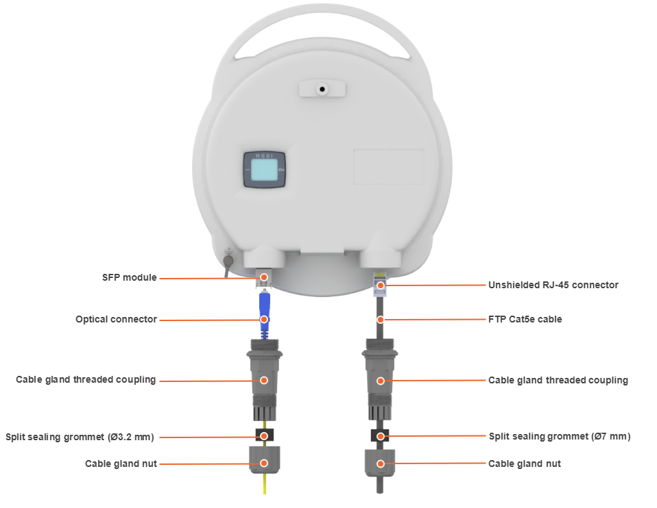
Required components are listed below.
- Unshielded RJ-45 connector.
- Shielded RJ-45 connector.
- FTP Cat5e cable.
- Cable gland:
- Cable gland nut.
- Split sealing grommet (with inner diameter 7 mm).
- Cable gland threaded coupling.
- Crimping tool for RJ-45 connector.
NOTE
The outside diameter value of the FTP Cat5e cable should not exceed 7 mm.
NOTE
Cable gland can be assembled on pre-crimped cable.
Assemble procedure
In order to ensure that the device case remains sealed under any environmental conditions follow the assemble procedure:
- Step 1: Crimp the standard RJ-45 connector onto the cable using crimping tool. Pin-out scheme: T568B wiring standard.
NOTE
Do not use the shielded RJ-45 connector on this end of the cable as it should be attached on the power supply unit end.
CAUTION
Make sure that the RJ-45 connector is well-crimped. A loose connector can damage the device. Please note that such damage is not covered by the warranty.
- Step 2: Assemble cable gland nut, the split sealing grommet and the cable gland threaded coupling onto the pre-terminated cable as shown on the figure below.
- Step 3: Insert the split sealing grommet into the cable gland threaded coupling.
- Step 4: Insert the RJ-45 connector into the device socket until you hear a click.
- Step 5: Screw the cable gland threaded coupling into the port and tighten it. Do not apply excessive force.
- Step 6: Tighten the cable gland nut (4). Do not apply excessive force.
Cable Gland Assembly for Optical Cable
Required components are listed below.
- Optical cable.
- Optical connector.
- SFP module.
- Cable gland:
- Cable gland nut.
- Split sealing grommet (with inner diameter 3.2 mm).
- Cable gland threaded coupling.
Assemble procedure
- Step 1: Put the cable gland nut, the split sealing grommet and cable gland threaded coupling onto the optical cable as shown on the figure below.
- Step 2: Insert the split sealing grommet into the cable gland threaded coupling.
- Step 3: Set the SFP module into the socket until you hear a click.
- Step 4: Insert the optical connector into the SFP module.
- Step 5: Screw the cable gland threaded coupling into the port and tighten it.
- Step 6: Tighten the cable gland nut. Do not apply excessive force.
NOTE
In order to disassemble SFP, please disconnect the optical cable, pull the clip of the SFP module and withdraw the SFP module from the slot.
NOTE
SFP module is not included into the packing list.