During link planning such factors as distance, obstacles and the link margin should be taken into account. We strongly recommend to use the InfiPLANNER tool for link planning.
InfiPLANNER
InfiPLANNER is a link planning tool, which allows to design networks using InfiNet Wireless devices for optimal deployment and cost effectiveness. It performs different scenarios based on geography, distance, antenna height, transmit power, device models and other factors. It outputs an installation report that defines the parameters to be used for configuration, alignment and operation. Use the installation report to compare predicted and actual link performance. InfiPLANNER is available at https://infiplanner.infinetwireless.com.
NOTE
You can find more detailed information about InfiPLANNER in the "InfiPLANNER: Link Planning Tool" online course.
Range and obstacles
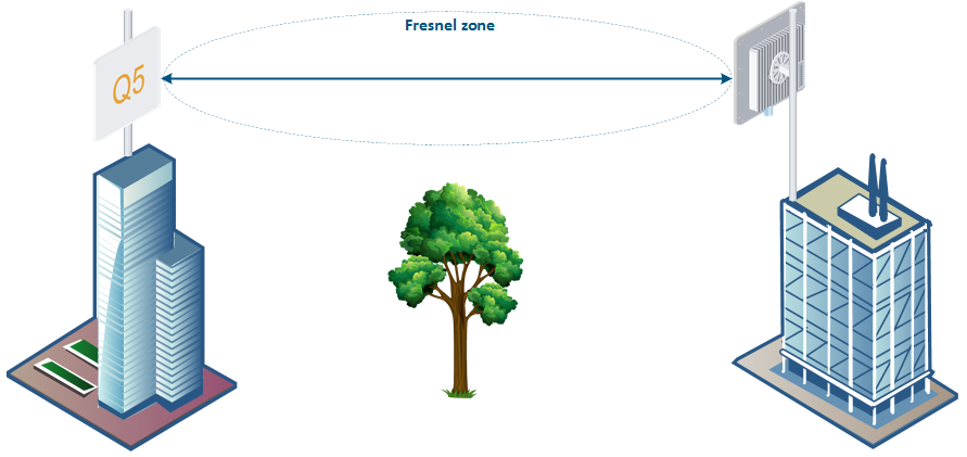
Make sure line of sight is provided during planning the antennas placement for a point-to-point link, to achieve maximum range and performance between two antennas. Perform a survey to identify all the obstructions (such as trees or buildings) in the path and to assess the risk of interference.
The radio beam is an invisible form of electromagnetic wave propagation and is not as thin as a laser beam, for example. The main energy in a radio beam is concentrated along the straight line between the two antennas, inside an area the shape of an ellipsoid (or a rugby ball). This area is called a 1st Fresnel zone and its exact form and size depends upon the frequency and the signal propagation path length.
If most of the 1st Fresnel zone is obstructed, a major part of the radio wave’s electromagnetic energy is lost, which leads to a severe signal quality degradation and as a result to decreased coverage range or performance.
Below is an incomplete list of possible obstructions on the signal propagation path:
- Neighboring buildings.
- Trees.
- Bridges.
- Power lines.
To obtain the best results, it is necessary to perform a precise analysis of the signal propagation path and possible obstructions that may cover the 1st Fresnel zone.
NOTE
More detailed information about radio signal propagation is available at "Wireless Networking Fundamentals" online course.
Antenna Placement
General recommendations for antenna placement:
- Try to keep the LOS clear of obstructions. In case of installations over vegetation and forest, make sure the direct LOS stays above the trees; in urban environments - above the tallest buildings along the radio path.
- The influence of trees can be variable, depending on seasons (ice, dew, leaves). Keep in mind that, during spring and summer, leaves can absorb high levels of radio energy. Therefore, when installing during the cold season, over forests and trees without leaves, try to achieve a higher fade margin.
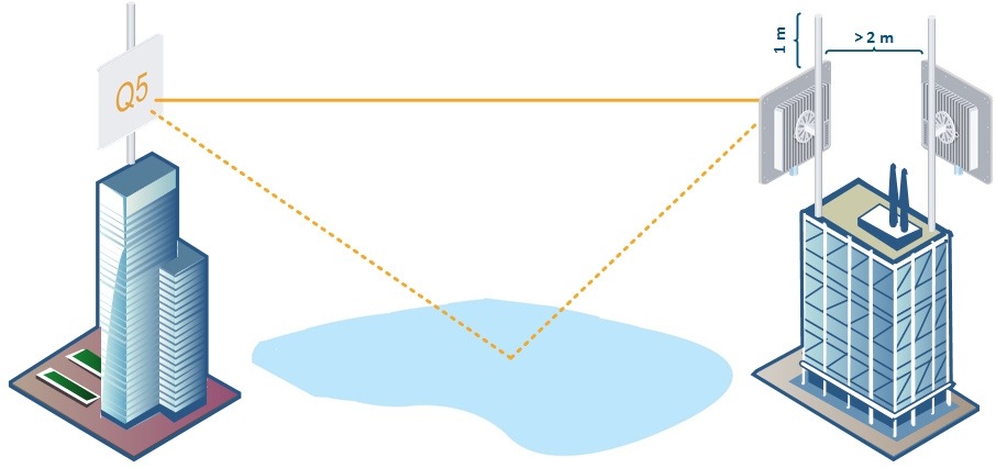
- Install antennas as far as possible from other antennas (the recommended distance is at least 2 meters).
- Reflecting surfaces should be considered (buildings with reflective windows, water surfaces or wet grounds). These can be useful in NLOS situations, if there is no direct clear path between the 2 antennas, so the radio signal needs to be reflected off a surface. However, these can also decrease the signal quality when encountered along a clear LOS link, because of fading caused by multipath.
- When installing antennas over water, tune the height bracket within 1-3 meters range variation, because it can yield significant signal level variations due to multipath fading.
- Weather factors such as rain or snow do not usually affect system performance. If seasonal changes influence the signal quality, then the connectors probably are not protected well enough from humidity, or the cables, connectors or antennas are covered by vegetation during summer or ice during winter.
NOTE

Changes or modifications not expressly approved by the party responsible for compliance could void the user’s authority to operate the equipment.
This equipment has been tested and found to comply with the limits for a Class B digital device, pursuant to part 15 of the FCC Rules. These limits are designed to provide reasonable protection against harmful interference in a residential installation. This equipment generates, uses and can radiate radio frequency energy and, if not installed and used in accordance with the instructions, may cause harmful interference to radio communications. However, there is no guarantee that interference will not occur in a particular installation. If this equipment does cause harmful interference to radio or television reception, which can be determined by turning the equipment off and on, the user is encouraged to try to correct the interference by one or more of the following measures:
- Reorient or relocate the receiving antenna.
- Increase the separation between the equipment and receiver.
- Connect the equipment into an outlet on a circuit different from that to which the receiver is connected.
- Consult the dealer or an experienced radio/TV technician for help.
NOTE
This device contains licence-exempt transmitter(s)/receiver(s) that comply with Innovation, Science and Economic Development Canada’s licence-exempt RSS(s). Operation is subject to the following two conditions:
- This device may not cause interference.
- This device must accept any interference, including interference that may cause undesired operation of the device.
This Class B digital apparatus complies with Canadian ICES-003.
Following also applies to this radio equipment:
- the band 5150–5250 MHz is only for indoor use to reduce the potential for harmful interference to co-channel mobile satellite systems;
- for devices with detachable antenna, the maximum antenna gain permitted for devices in the bands 5250-5350 MHz and 5470-5725 MHz shall be such that the equipment still complies with the e.i.r.p. limit;
- for devices with detachable antenna, the maximum antenna gain permitted for devices in the band 5725-5850 MHz shall be such that the equipment still complies with the e.i.r.p. limits as appropriate; and
- where applicable, antenna type(s), antenna models(s), and worst-case tilt angle(s) necessary to remain compliant with the e.i.r.p. elevation mask requirement set forth in section 6.2.2.3 of the RSS-247 shall be clearly indicated.
High-power radars are allocated as primary users (i.e. priority users) of the bands 5250-5350 MHz and 5650-5850 MHz and these radars could cause interference and/or damage LE-LAN devices.