- Unpack the equipment.
- Check items integrity.
- Prepare RF cables of the required length. For 5GHz devices the recommended maximal RF cable length is 1 meter.
- Install and isolate the connectors on the RF cable.
Determine the FTP cable length that is used to connect IDU and ODU. The total cable length between LAN (behind IDU) and ODU should not be longer than 100 meters. Service cable connecting IDU and ODU should be FTP Cat5e cable with the outside diameter value not more than 7mm.
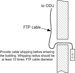 Figure - Installation scheme
- Install (solder) connector for ODU on the FTP cable and isolate it.
- If it is possible to lay FTP cable with a connector on the IDU side, install (solder) connector for IDU on the FTP cable and isolate it.
- Lay the FTP cable “from top to bottom” – from ODU to IDU.
- If step 7 is not accomplished, after the FTP cable has been laid, install (solder) connector for IDU.
- Install ODU on the mounting bracket connectors down and tighten it.
- Connect the ODU-IDU cable to the ODU.
- Isolate the ODU connector joint place.
- Once the antenna and antenna pole are installed they must be grounded via lightning protection grounding contour. Antenna’s position must be lower than the highest antenna pole point at least by 2 antenna heights. If antenna is NOT DC-shorted (see antenna technical documentation), the additional lightning protection unit must be used which is placed between ODU and antenna and is grounded to the antenna pole grounding contour.
- Connect RF cable to the antenna. Twist the connector tightly.
- Connect RF cable to the ODU previously having touched RF cable connector case with ODU connector case.
Isolate RF connectors from both sides (ODU and antenna).
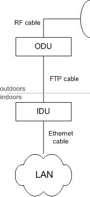 Figure - Connection scheme
- Connect the FTP cable to IDU previously having touched IDU connector case with FTP cable connector case.
- Provide grounding for IDU.
- Connect Ethernet cable to IDU.
- Provide power supply for IDU.
- Connect to the Router using Telnet protocol.
NOTE
It is extremely important to install ODU connectors down!
CAUTION
In order to prevent device damage make sure that antenna is connected to both N-type connectors with serviceable RF cables before switching on.
During laboratory testing, it is allowed to directly connect two devices with RF cables without antennas with the mandatory use of attenuators with attenuation of at least 40 dB for each polarization. Switching off/on the attenuators and RF cables should only be performed when the devices are in the off state.
In case the antenna or other device is connected to only one N-type connector do not switch on the device.
PLEASE NOTE THAT VIOLATION OF THE ABOVE REQUIREMENTS VOIDS THE WARRANTY.