Успешно сдайте бесплатный сертификационный экзамен в Академии "Инфинет" и получите статус сертифицированного инженера Инфинет.
Перед установкой оборудования на площадке, рекомендуется произвести первичную настройку в лаборатории, чтобы убедиться, что канал связи устанавливается. Достаньте устройства из упаковки и разместите на столе.
ВНИМАНИЕ
При настройке устройств в лабораторных условиях следует учесть следующие требования:
- Устройства должны быть расположены таким образом, чтобы они не были направлены непосредственно друг на друга во избежание повреждения радиомодулей.
При настройке устройств с внешними антеннами рекомендуется соединять устройства в канал связи напрямую, используя высокочастотные кабели и аттенюаторы с затуханием не менее 40 дБ по обеим поляризациям (сборка/разборка высокочастотных кабелей и аттенюаторов должна производиться только при выключенных устройствах only be performed when the devices are switched off).
Не включайте устройства если внешняя антенна или другое устройство подключено только к одному из разъёмов N-типа.
Этап 1: Соберите тестовый стенд
Для настройки вам понадобятся следующие компоненты:
- Внешний блок - 2 шт.
- Источник питания - 2 шт.
- Кабель питания - 2 шт.
- Кабель Ethernet - 4 шт.
- Ноутбук.
Применим схему описанную ниже на всех устройствах и убедимся что беспроводной канал связи устанавливается.
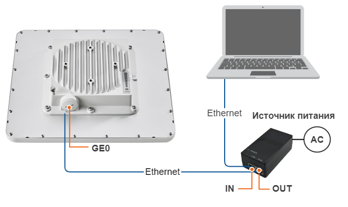
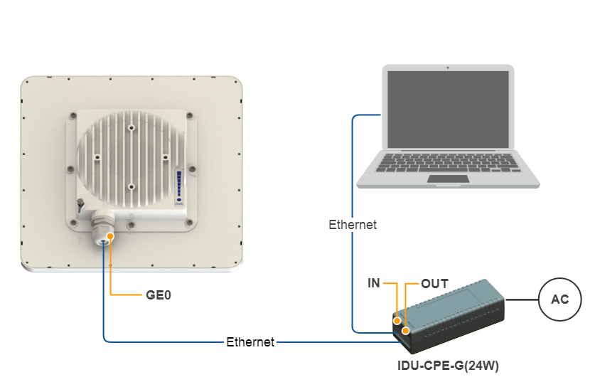
Соберите схему для настройки в следующей последовательности:
- Соедините кабелем порт Ethernet на внешнем блоке и порт "OUT" на иcточнике питания.
- Соедините кабелем порт Ethernet на ноутбуке и порт "IN" на источнике питания.
- Подключите кабель питания к источнику питания и включите его в сеть переменного тока.
Step 2: Access to the device
Let's access each unit to the default IP address 10.10.10.1 with mask 255.255.255.0 via a web browser. Before, make sure the Ethernet port of the Laptop has an IP address assigned from the same subnetwork as the one for the unit (e.g., set 10.10.10.10 with mask 255.255.255.0).
NOTE
We assume that each unit used in this setup has not been configured before and runs with the factory settings.
Use any letters or numbers for the initial authentication on each unit, for example:
- Login: login.
- Password: password.
NOTE
We strongly recommend to change your login and password after the first login.
After the first login, let's configure a distinctive name for each unit and set a custom login and password. Go to the Basic Settings section, then to System Settings and configure::
- Device Name (e.g., Master/Slave).
- User Name (e.g., admin).
- Password (e.g., admin).

NOTE
At the next login set up login and password to access the unit in the privileged mode.
Step 3: Management IP change
Let's change the management IP of each unit. Go to the "Basic Settings" section, then to Network Settings and change the default IP address of the ‘svi’ interface which is a logical interface used for remote management access in MINT switching mode (MINT switching mode is enabled by default).
Network settings for Master:

Network settings for Slave:
Step 4: Software upgrade
Let's upgrade each unit to the latest stable firmware version. Go to the Maintenance section and click on the "Check Latest Release" button. In case a new software version is available, click on the "Upgrade Firmware" to initiate the firmware upgrade process. Before, make sure the laptop which is connected to the unit has an Internet connection, too. Otherwise, the manual firmware upgrade process should be performed.

Step 5: Radio parameters configuration
Let's configure the minimum needed radio parameters to establish the link.
At the unit named Master at step #3 above, go to the "Basic Settings" section, then to "Link Settings" and set this unit with:
- Type: Master.
- Polling: On.
- Tx Power: e.g., -10 dBm (set the minimum value in the range, as currently, we are in the lab, and we don't need high output power anymore).
- Node Name: e.g., Master (it is the same as the value set at Device Name if this was saved before).
- Channel Width: e.g., 40 MHz.
- Frequency: e.g., 4900 MHz.
- Greenfield: On.
The rest of parameters remain with the default values.

At the unit named Slave at step #3 above, go to the Basic Settings section, then to Link Settings and set this unit with:
- Type: Slave.
- Tx Power: e.g., 5 dBm (set the minimum value in the range, as currently, we are in the lab, and we don't need high output power anymore).
- Node Name: e.g., Slave (it is the same as the value set at Device Name if this was saved before).
- Channel Width: e.g., 40 MHz.
- Frequency: e.g., 4900 MHz.
- Greenfield: On.
The rest of parameters remain with the default values.

Step 6: Check the wireless link status
Let's apply all settings described above for each unit and after login let's go to the Device Status section, and check the link establishment at Link Statistics.
Master Link Statistics:

Slave Link Statistics:
