Успешно сдайте бесплатный сертификационный экзамен в Академии "Инфинет" и получите статус сертифицированного инженера Инфинет.
Грубая юстировка
Чтобы засечь сигнал удалённой стороны, используйте азимут и угол места полученный из отчёта, предоставленного инструментом планирования InfiPLANNER. Оценить наличие установленного беспроводного канала связи и его качество можно используя светодиодную индикацию на корпусе устройства. Светодиодная индикация подробно описана в разделе "Аппаратная платформа". Для более точной юстировки используйте специальный инструмент юстировки, встроенный в веб-интерфейс устройства.
Точная юстировка
Оптимально проводить юстировку двумя командами по два человека. Первый будет считывать данные об уровне сигнала и осуществлять взаимодействие с командой на противоположной стороне канала связи. Второй человек будет производить манипуляции с антенной. После начальной ориентации устройство на удалённом конце необходимо зафиксировать. Сначала юстировка выполняется устройства с наименьшим коэффициентом усиления антенны, затем для другого.
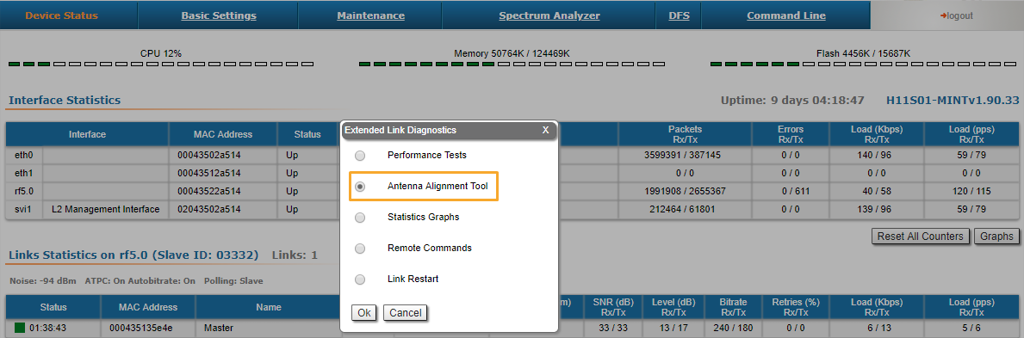
Обе команды используют для точной юстировки web-интерфейс. Для этого в разделе "Состояние" - "Статистика линков для интерфейса rf5.0", кликните левой кнопкой мыши по каналу связи, для которого производится юстировка, выберите опцию "Юстировка антенны".
Команда, антенна которых имеет больший коэффициент усиления, медленно меняет азимут, отслеживая изменения показателей уровня сигнала.
- При достижении максимальных значений показателей (индикатор уровня принимаемого сигнала должен находиться как можно ближе к центру чёрной зоны) необходимо зафиксировать антенну.
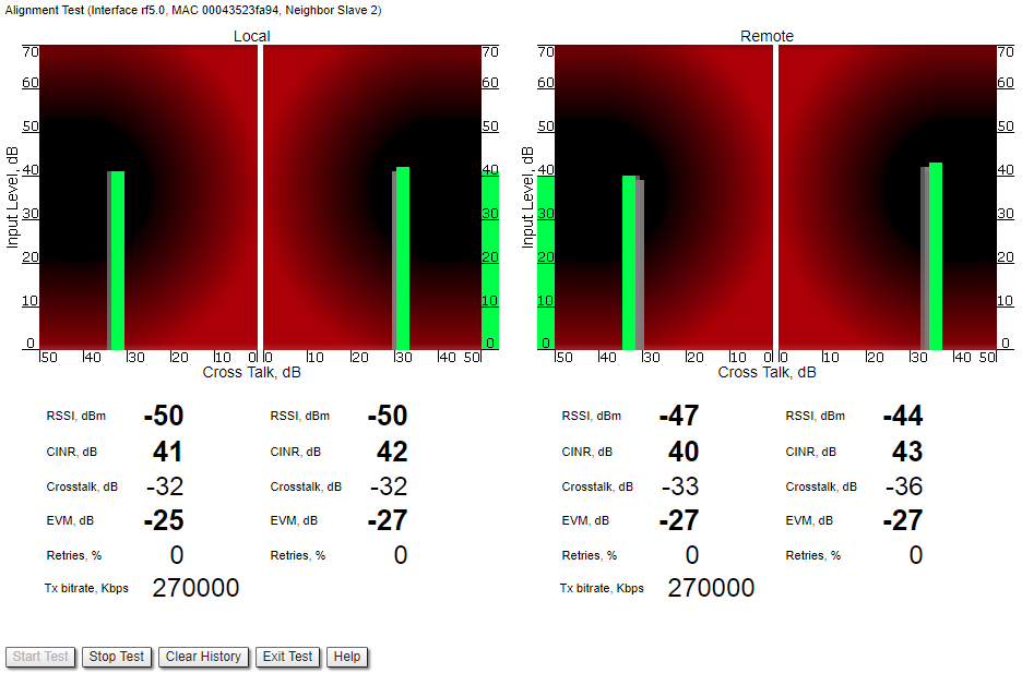
- The same action will be performed for the elevation, and the antenna must be locked into the final position where both elevation and azimuth provide the best signal, according to the indicators provided by the antenna alignment tool:
- EVM: higher than 21 in absolute value.
- Signal level to interference and noise: higher than 28 dB.
- Retries: lower than 10 %.
CAUTION
No contact should be made with the antennas during signal reading because the human body can affect the radiation pattern of the antenna and signal readings.
The main parameters displayed in the alignment tool:
- RSSI - indicates the power level of the received radio signal, optimal parameter value -60 ... -40 dBm.
- CINR - input signal level to noise + interference indicator, >=28 dB.
- Crosstalk - indicates how much vertically and horizontally polarized signals influence each other, >20 dB in absolute value.
- Error Vector Magnitude (EVM) - indicator of the measured input signal quality (it should be as high as possible in absolute value, the recommended level is not less than 21 dB in absolute value. Some old firmware had EVM value positive, but most the firmware has negative value, so for the troubleshooting, evaluate the absolute EVM value) .
- Retries - percentage of transmit packet retries (measured in %), <10.
- Tx bitrate - displays the current bitrate for the remote and local units (measured in Kbps).
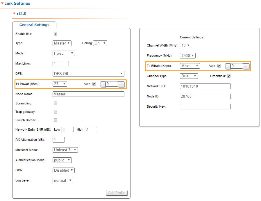
As soon as the antennas have been precisely alignment, set the "auto" option for Tx power and bitrate at both units, bearing in mind the EIRP limitations.
Depending on the values for SNR, RSSI, retries and current bitrate, change the following parameters:
- Decrease/increase the Tx power level (keeping the auto option checked) to have the SNR at around 25 dB and the RSSI at around -55 dBm.
- Decrease the bandwidth to lower the noise and to increase the SNR to above 20 dB.
Wireless link statistics
- Let's check the link parameters (for the correct link model according to the link distance, with an optimal antennas alignment, clear working frequency, and Clear-Line-of Sight, the values displayed must be the optimal ones for that particular link).
- Go to the Device Status section and in the Link Statistics, check the Level Rx/Tx and Retries Rx/Tx:
- Retries Rx/Tx: maximum 5 %.
- Level Rx/Tx: minimum 20 dB.

NOTE
If the two conditions above are not met, decrease the bandwidth from 40 MHz to 20 MHz, or even to 10 MHz, to lower the noise and to increase the SNR to above 20 dB.
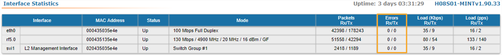
Interface statistics
- Let's check the number of Rx/Tx errors for the Ethernet and Radio interfaces are close to “0”, which is the case for an optimal link establishment (no traffic is generated through the wireless link at this stage).
- Go to the Device Status section and in the Interface Statistics for eth0 and rf5.0 interfaces, check the Errors Rx/Tx.