Successfully pass the free certification exam at IW Academy and become an Infinet Certified Engineer.
Description
The main scenario for organizing the connection with mobile objects is the following (see Figure 1):
- The base stations BS1, BS2 and BS3 are installed along the area perimeter, forming the backhaul radio network. Single-sector base station configurations are used, i.e. each BS has one sector. Non-overlapping frequency channels are configured on the base station sectors.
- A mobile object moves within the backhaul radio network from point A to point B. A subscriber terminal, CPE1, is installed on the mobile object. Depending on the requirements for the connection reliability, there are two implementation options: the installation of one subscriber with an antenna having a circular radiation pattern, or the installation of two subscribers on each moving object. During the motion, CPE1 can establish a radio link with the devices of the backhaul radio network - BS1, BS2 and BS3.
- The aggregation node is located near BS2, where the InfiMUX is installed. All BSs sectors are connected to the InfiMUX, which joins the radio backhaul network devices into a single MINT area.
- The aggregation node and the enterprise LAN are connected via the Master-Slave backbone link.
- The Global function is enabled on CPE1 and on the InfiMUX.
- "Mode nomadic" is set on the backhaul radio network devices and on CPE1, "mode fixed" - on the Master and Slave devices. Depending on the project specifics, other mode values may be set.
- For device management, VLAN 100 is reserved, which is associated with the 192.168.100.0/24 subnet.
- VLAN 200 is used for the data transmission service.
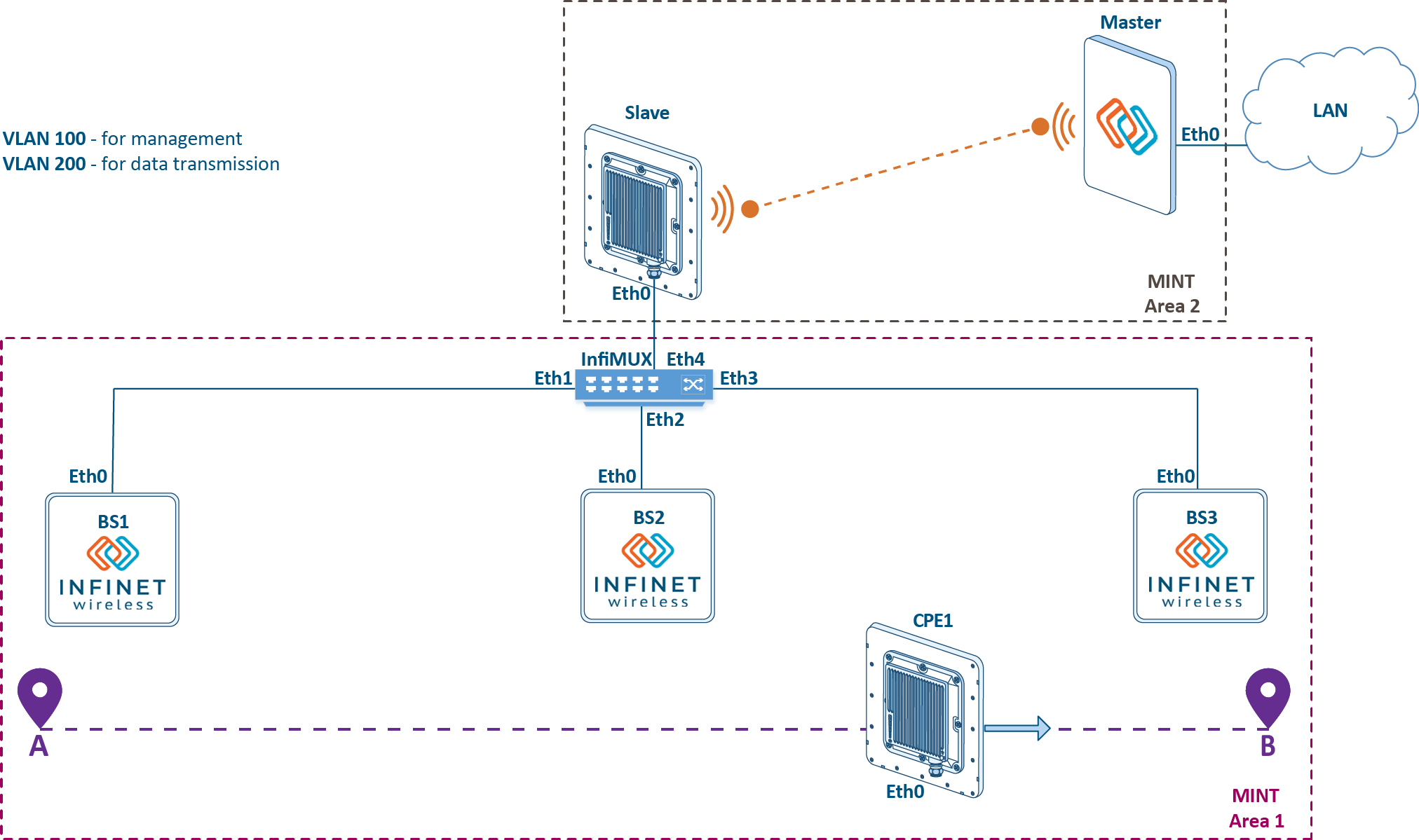
Figure 1 - Example of a project with mobile objects
Planning
Radio and data settings are in table below:
Table 1 - Radio settings for a project with mobile objects
| Device name | Center frequency | Channel width | Role |
|---|---|---|---|
| Master | 5000 | 20 | master |
| Slave | 5000 | 20 | slave |
| BS1 | 5100 | 20 | master |
| BS2 | 5200 | 20 | master |
| BS3 | 5300 | 20 | master |
CPE1 | 5100 | 20 | slave |
| 5200 | 20 | slave | |
| 5300 | 20 | slave |
Table 2 - data transfer settings for project with mobile objects
| Device name | SVI interface IP address | VLAN | Switch groups | Global | Mode |
|---|---|---|---|---|---|
| Master | 192.168.100.201/24 | 100,200 | 100,200 | no | fixed |
| Slave | 192.168.100.202/24 | 100,200 | 100,200 | no | fixed |
| InfiMUX | 192.168.100.200/24 | 100,200 | 100,200 | yes | nomadic |
| BS1 | 192.168.100.1/24 | 100,200 | 100 | no | nomadic |
| BS2 | 192.168.100.2/24 | 100,200 | 100 | no | nomadic |
| BS3 | 192.168.100.3/24 | 100,200 | 100 | no | nomadic |
| CPE1 | 192.168.100.101/24 | 100,200 | 100,200 | yes | nomadic |
Configuration
Devices configuration via CLI:
configure the radio parameters:
Master device radio configuration example#Radio module parameters rf rf5.0 band 20 rf rf5.0 mimo rf rf5.0 freq 5000 bitr auto sid 10101010 burst rf rf5.0 txpwr max pwrctl distance auto #MINT configuration mint rf5.0 -name "Master" mint rf5.0 -type master mint rf5.0 -mode fixed mint rf5.0 start
Slave device radio configuration example#MINT configuration mint rf5.0 -name "Slave" mint rf5.0 -type slave mint rf5.0 -mode fixed mint rf5.0 prof 1 -band 20 -freq 5000 -sid 10101010 -type slave -autobitrate -mimo mint rf5.0 start
BS1 device radio configuration example#Radio module parameters rf rf5.0 band 20 rf rf5.0 mimo rf rf5.0 freq 5100 bitr auto sid 10101010 burst rf rf5.0 txpwr max pwrctl distance auto #MINT configuration mint rf5.0 -name "BS1" mint rf5.0 -type master mint rf5.0 -mode nomadic mint rf5.0 start
BS2 device radio configuration example#Radio module parameters rf rf5.0 band 20 rf rf5.0 mimo rf rf5.0 freq 5200 bitr auto sid 10101010 burst rf rf5.0 txpwr max pwrctl distance auto #MINT configuration mint rf5.0 -name "BS2" mint rf5.0 -type master mint rf5.0 -mode nomadic mint rf5.0 start
BS3 device radio configuration example#Radio module parameters rf rf5.0 band 20 rf rf5.0 mimo rf rf5.0 freq 5300 bitr auto sid 10101010 burst rf rf5.0 txpwr max pwrctl distance auto #MINT configuration mint rf5.0 -name "BS3" mint rf5.0 -type master mint rf5.0 -mode nomadic mint rf5.0 start
CPE1 device radio configuration example#MINT configuration mint rf5.0 -name "AS1" mint rf5.0 -type slave mint rf5.0 -mode nomadic mint rf5.0 prof 1 -band 20 -freq 5100 -sid 10101010 -type slave -autobitrate -mimo mint rf5.0 prof 2 -band 20 -freq 5200 -sid 10101010 -type slave -autobitrate -mimo mint rf5.0 prof 3 -band 20 -freq 5300 -sid 10101010 -type slave -autobitrate -mimo mint rf5.0 start
join the backhaul radio network devices into a single MINT area:
BS1 configuration example#Interfaces parameters ifc prf0 up #Pseudo-RF parameters prf 0 parent eth0 #MINT configuration mint prf0 -name "BS1_prf_eth0" mint prf0 -type master mint prf0 -mode nomadic mint prf0 start mint join rf5.0 prf0
BS2 configuration example#Interfaces parameters ifc prf0 up #Pseudo-RF parameters prf 0 parent eth0 #MINT configuration mint prf0 -name "BS2_prf_eth0" mint prf0 -type master mint prf0 -mode nomadic mint prf0 start mint join rf5.0 prf0
BS3 configuration example#Interfaces parameters ifc prf0 up #Pseudo-RF parameters prf 0 parent eth0 #MINT configuration mint prf0 -name "BS3_prf_eth0" mint prf0 -type master mint prf0 -mode nomadic mint prf0 start mint join rf5.0 prf0
InfiMUX configuration example#Interfaces parameters ifc prf1 up ifc prf2 up ifc prf3 up #Pseudo-RF parameters prf 1 parent eth1 prf 2 parent eth2 prf 3 parent eth3 #MINT configuration mint prf1 -name "InfiMUX_prf_eth1" mint prf1 -type master mint prf1 -mode nomadic mint prf1 start mint prf2 -name "InfiMUX_prf_eth2" mint prf2 -type master mint prf2 -mode nomadic mint prf2 start mint prf3 -name "InfiMUX_prf_eth3" mint prf3 -type master mint prf3 -mode nomadic mint prf3 start mint join prf1 prf2 prf3
enable the Global function:
Global function configuration on CPE1#MINT configuration mint rf5.0 roaming enable global
Global function configuration on InfiMUX#MINT configuration mint prf0 roaming enable global
configure the management:
Management configuration on Master#Interfaces parameters ifc vlan100 vlan 100 vlandev eth0 up ifc svi100 up ifc svi100 192.168.100.201/24 #MAC Switch config switch group 100 add vlan100 rf5.0 switch group 100 order 1 switch group 100 start #Switch Virtual Interface config svi 100 group 100
Management configuration on Slave#Interfaces parameters ifc vlan100 vlan 100 vlandev eth0 up ifc svi100 up ifc svi100 192.168.100.202/24 #MAC Switch config switch group 100 add vlan100 rf5.0 switch group 100 order 1 switch group 100 start #Switch Virtual Interface config svi 100 group 100
Management configuration on BS1#Interfaces parameters ifc svi100 up ifc svi100 192.168.100.1/24 #MAC Switch config switch group 100 add prf0 switch group 100 order 1 switch group 100 start #Switch Virtual Interface config svi 100 group 100
Management configuration on BS2#Interfaces parameters ifc svi100 up ifc svi100 192.168.100.2/24 #MAC Switch config switch group 100 add prf0 switch group 100 order 1 switch group 100 start #Switch Virtual Interface config svi 100 group 100
Management configuration on BS3#Interfaces parameters ifc svi100 up ifc svi100 192.168.100.3/24 #MAC Switch config switch group 100 add prf0 switch group 100 order 1 switch group 100 start #Switch Virtual Interface config svi 100 group 100
Management configuration on CPE1#Interfaces parameters ifc svi100 up ifc svi100 192.168.100.101/24 #MAC Switch config switch group 100 add rf5.0 switch group 100 order 1 switch group 100 start #Switch Virtual Interface config svi 100 group 100
Management configuration on InfiMUX#Interfaces parameters ifc vlan100 vlan 100 vlandev eth4 up ifc svi100 up ifc svi100 192.168.100.200/24 #MAC Switch config switch group 100 add vlan100 prf1 switch group 100 order 1 switch group 100 start #Switch Virtual Interface config svi 100 group 100
configure the service trafic transmission:
Master configuration example#Interfaces parameters ifc vlan200 vlan 200 vlandev eth0 up #MAC Switch config switch group 200 add vlan200 rf5.0 switch group 200 start
Slave configuration example#Interfaces parameters ifc vlan200 vlan 200 vlandev eth0 up #MAC Switch config switch group 200 add vlan200 rf5.0 switch group 200 start
CPE1 Master configuration example#Interfaces parameters ifc vlan200 vlan 200 vlandev eth0 up #MAC Switch config switch group 200 add vlan200 rf5.0 switch group 200 start
InfiMUX configuration example#Interfaces parameters ifc vlan200 vlan 200 vlandev eth4 up #MAC Switch config switch group 200 add vlan200 prf1 switch group 200 start