Successfully pass the free certification exam at IW Academy and become an Infinet Certified Engineer.
In the "Network Settings" section, there are displayed all physical and logical network interfaces that are already configured. The physical interfaces (eth0 and rf5.0) are set by default and they cannot be removed. For these two interfaces, you are allowed to change the parameters only.
NOTE
Before making the configurations in the "Network Settings" section, please read the information presented in the "MAC Switch" section.
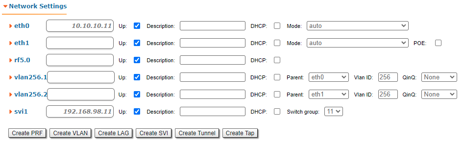
For the following layer 2 and 3 logical interfaces, you are allowed to add (by clicking the corresponding buttons and specifying the interface number), remove and change the parameters of the interface:
- "PRF" - Pseudo Radio Interface can be attached to the Ethernet interface in order to allow it to work as a radio interface using the MINT protocol, so that the node can find its neighbors and establish the links with them through this interface. The interface encapsulates MINT-frames into the Ethernet-frames and allows connecting the units of the MINT network using wired interfaces. Also, this interface can be joined with other interfaces;
- "VLAN" can be assigned to a physical interface or to a virtual interface sviX. It is used for the creation of the logical network topology regardless of the physical topology of this network. VLAN allows creating groups of interfaces which have a common set of requirements. It contributes to reducing the multicast traffic in the network, as every VLAN is a separate multicast domain. VLAN usage increases the network security and manageability;
- "LAG" can be assign to two physical interfaces in order to use them as one logical interface for total throughput increasing and system reliability improving. The total throughput of the logical channel represents the sum of the capabilities of associated physical interfaces. In case of failure of any physical channel included in the logical channel, the system will continue to operate, using the rest operable physical channels. Interface allows creating high speed links (between the unit and the network switch, for example) by means of aggregation of the two available Ethernet-interfaces of the unit (it is intended for Smn/Lmn units with 2 Ethernet ports);
- "SVI", Switch Virtual Interface is an L3 interface that can be assigned to a switching group for getting access to the unit management via this switching group. This interface becomes part of this switching group and can participate in the exchange of information with other group members so that any packets received by the group (according to its rules), or addressed to the sviX directly, or copies of multicast/broadcast packets, will be received by the unit through the "sviX". This interface allows getting the remote access to the unit management. It is also used for the Management VLAN configuration;
- "Tunnel" is implemented like a PtP link between two routers that encapsulates the flow into the IP packets and send it to the end point of the link using the existing transport environment. It allows to unite two remote networks (which are not directly connected) in an integrated logical structure (VPNs) which use its own network address allocation and account policies, independent from the ones supplied by the service providers for each of the separate network segments;
- "TAP" interface simulates a link layer (L2) device and operates with Ethernet frames. TAP interface is used for creating a network bridge.
| Interface type | Operations |
|---|---|
| ethX |
|
| rfX |
|
| sviX |
|
| prfX |
|
| vlanX |
|
| lagX |
|
| tunX |
|
| tapX |
|
Click the «Create PRF», «Create VLAN», «Create LAG» and «Create SVI» buttons in order to create the corresponding interfaces in the unit configuration.
In the "Network Settings" section, "Routing Parameters" zone, you can configure the static routes:
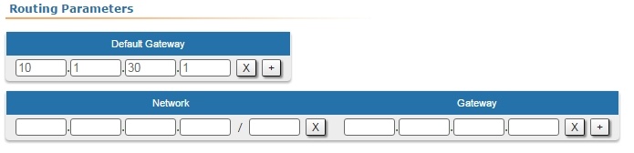
- In the “Network” field, you can configure the destination network IP-address
- In the “Gateway” field, you can configure the IP-address of the router through which the network address is reachable.
As all wireless MINT interfaces are in one virtual Ethernet segment, they can be enumerated by assigning IP addresses from one IP subnet (manually or automatically, via DHCP). Thus, getting to one node (via telnet, for example), you can access all the other nodes. The access from the “outside” network can be established by configuring the necessary routing, so that the “inner” MINT network can be accessible from the administrator’s computer through the Ethernet port of the MINT node which is connected to the “outside” network. From the “inner” MINT network, the route to the administrator’s computer should go through the radio-interface to the border router.
NOTE
Read the information in the section "Apply, Try and Preview buttons for the configuration" in order to find out the output of the «Apply», «Test» and «Preview» buttons for the new configuration performed.