Successfully pass the free certification exam at IW Academy and become an Infinet Certified Engineer.
InfiNet Wireless R5000-Smn
Detailed information about each R5000-Smn part number you can find at InfiNet Wireless web-site: InfiLINK 2x2 (PtP products) and InfiMAN 2x2 (PtMP products)
InfiNet Wireless R5000-Smn units top views with indicator panels are below:
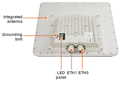
Device status description according to LED modes is given in section "ODU LED indicators description".
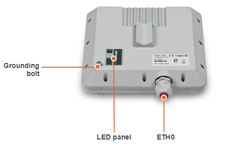
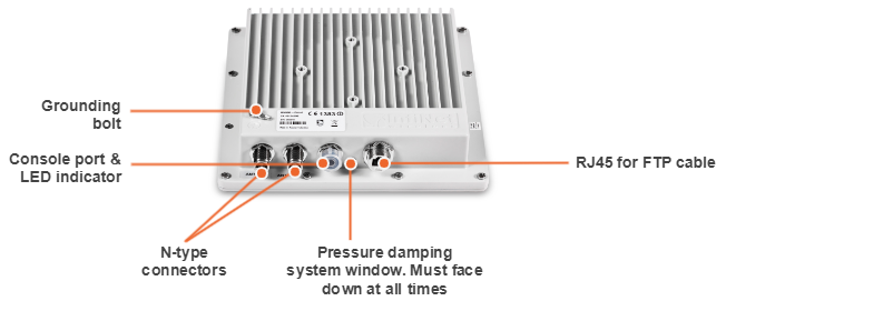
InfiNet Wireless R5000-Lmn
Detailed information about each R5000-Lmn part number you can find at InfiNet Wireless web-site: InfiLINK 2x2 (PtP products) and InfiMAN 2x2 (PtMP products).
InfiNet Wireless R5000-Lmn units top view with indicator panel is below:
Device status description according to LED modes is given in section "ODU LED indicators description".
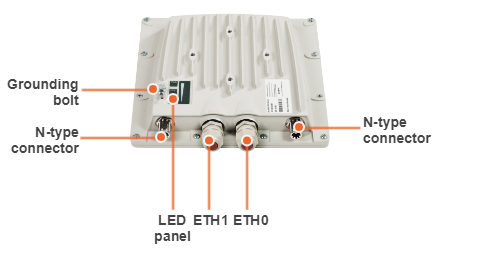
InfiNet Wireless R5000-Qmxb
Detailed information about each R5000-Qmxb part number you can find at InfiNet Wireless web-site: InfiMAN 2x2 (PtMP products).
InfiNet Wireless R5000-Qmxb units front panel view is below:
Device status description according to LED modes is given in section "ODU LED indicators description".
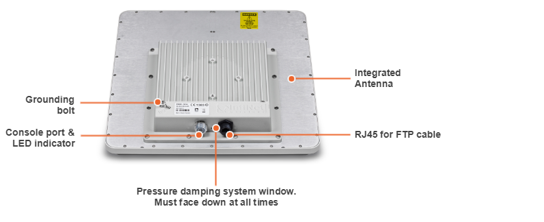
InfiNet Wireless R5000-Mmx
Detailed information about each R5000-Mmx part number you can find at InfiNet Wireless web-site: InfiLINK 2x2 (PtP products) and InfiMAN 2x2 (PtMP products).
InfiNet Wireless R5000-Mmx units front panel view is below:

Device status description according to LED modes is given in section "ODU LED indicators description".
InfiNet Wireless R5000-Omx
Detailed information about each R5000-Omx part number you can find at InfiNet Wireless web-site: InfiLINK 2x2 (PtP products) and InfiMAN 2x2 (PtMP products).
InfiNet Wireless R5000-Omx units front panel view is below:
Device status description according to LED modes is given in section "ODU LED indicators description".
ODU LED indicators description
R5000-Qmxb, R5000-Mmx and R5000-Omx models have two LED indicators (red and green) located in the Console connector. These LEDs are useful in monitoring the device status during the installation procedure. LEDs modes and Device status correspondence is shown in the following table:
| Red indicator | Green indicator | Device status |
|---|---|---|
| Off | Off | Device is switched off of in the process of start-up booting |
| Off | Blinking | Device is booted. No radio connection. Searching for another device to establish radio connection to |
| Blinking | On | Radio connection established. The more data is transmitted through the radio channel the more frequently red indicator is blinking |
R5000-Smn and R5000-Lmn models have a special LED indicator set located at the back of each device designed to provide basic status information:
| LED | Status | Device Status |
|---|---|---|
| PWR | On | The device is powered on |
| RF | Blinking | RF-link is being established |
| On | RF-link established | |
| ETH | On | Wired link established |
| Signal level | This scale displays current RF signal level and is designed to provide assistance in device alignment and link quality estimation. The scale is based on the SNR RX level, the threshold values for the indicator: 4, 8, 16, 30, 40 dB. The more often indicator flashes, the better quality of the connection. |
Part number description
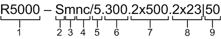
Structure items are described below
| Item | Description |
|---|---|
| 1 |
|
| 2 |
|
| 3 |
|
| 4 |
|
| 5 |
|
| 6 |
|
| 7 |
|
| 8 |
|
| 9 |
|
NOTE
Units may also be marked as “LITE” and “PRO”, where "PRO" - units that operate at greater distance and with higher performance. "LITE" refers to R5000-Smn and R5000-Lmn models, "PRO" - R5000-Mmx and R5000-Omx.