...
In order to access each of the units, we have to make sure that there is network connectivity between the PC used for the configurations and the units on their default Ethernet IP address which is 10.10.20.1/24.
...
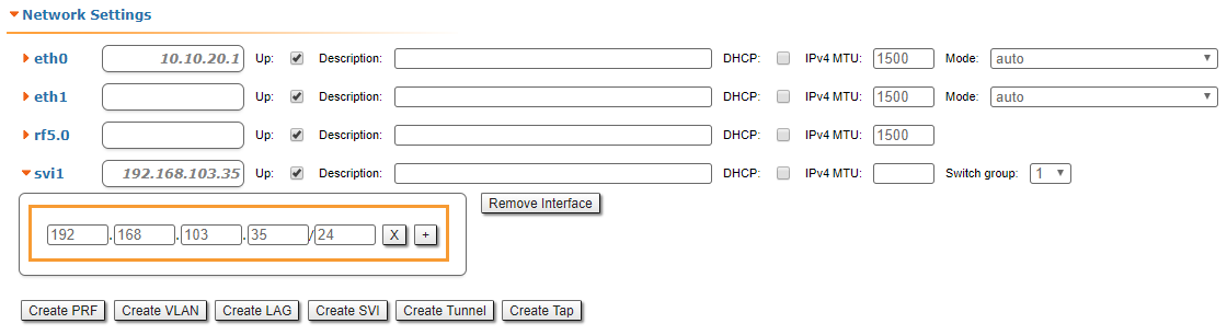
In "Basic Settings" → "Network Settings" section, we can change the default IP address of the svi1 interface. Let’s add the IP 192.168.1.1/24 for the first unit and the IP 192.168.1.2/24 for the second unit:
...
In "Basic Settings" → "Link Settings" section let’s configure the following radio parameters for the first unit:
- Type: Master
- Polling: On
- DFS: Off
- Node ID: 1
- Channel width: 40 MHz
- Frequency: 5870 MHz
...
- In "System Settings" section
- Device Name: Node2
- User Name: Node2
- Password: Infi2
- In "Network Settings" section
svi1 IP address: 192.168.1.2/24
In "Link Settings" section
- Type: Slave
- Node ID: 2
- Channel width: 40 MHz
- Frequency: 5870 MHz
...
We connect now back to the first unit at the IP 192.168.1.1/24, and go to "Device Status" menu in order to check the link establishment between our two units and all real-time parameters provided by Web interface:
| Center | |||||
|---|---|---|---|---|---|
|
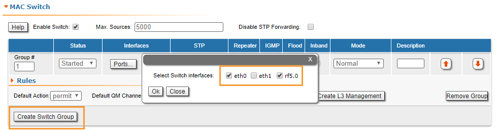
- Step 9
R5000 family devices allows to control data transfer using switch groups concept. We have to create a switch group 1, which will pass tagged and untagged traffic (this group is created by default). In the "MAC-Switch" section create a switch group 1 by clicking the "Create a switch group" button, add the Ethernet and Radio interfaces by clicking the "Ports" button.
| Center | |||||
|---|---|---|---|---|---|
|
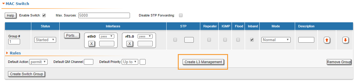
- Step 10 (optional)
To ensure device management not only via the wired segment, but also by radio, let's create an svi interface. Click the "Create L3 Management" button, and assign an IP address selected for device management. For more information about remote management, see the "Remote management of the R5000 units" article.
| Center | |||||
|---|---|---|---|---|---|
|
| Center | |||||
|---|---|---|---|---|---|
|