| Include Page | ||||
|---|---|---|---|---|
|
| Table of Contents |
|---|
Introduction
Scaling and increasing the performance of the wireless communication systems in the 5 GHz frequency range required an increase in the allowed frequency channels number by additionally using the channels that were initially assigned only for military and meteorological radars data transmission. To reduce the impact of the wireless broadband systems on radars, the data exchange protocol included requirements for detecting radar signals and immediately leaving clearing the operating frequency it operates.
The implementation of the radar detection mechanisms implementation was connected with related to the air scanning methods and to the transition between the frequency channels. These methods were included in the requirements for the operation of the wireless systems and were called dynamic frequency selection (DFS).
Dynamic frequency selection and radar detection
It is necessary to separate the mechanisms of point out the differences between the dynamic frequency selection technology and the radar detection mechanism:
- The dynamic frequency selection implementation require requires scanning the available frequency channels scanning and selecting the selection of the least noisy channel. Thus, DFS performs a uniform distribution of the wireless data transmission systems distribution over the frequency spectrum is performed.
- A radar detection mechanism is necessary to a ban the use of the frequency channels that radars operate onon which radars are currently operating. Thus, the DFS technology retains the possibility of using such channels by for the broadband wireless systems, in case as long as they are immediately released when radar operation is detected.
Regulatory requirements
Regulatory requirements for wireless communication systems vary by country. The The most common requirements for the implementation of dynamic frequency selection and radar detection in devices, were formed created by the Federal Communications Commission (FCC) and by the European Telecommunications Standards Institute (ETSI). It is described by following standards:
- ITU-R M.1652 – describing the performance requirements for the wireless systems in order to meet the detection and response demands;
- ETSI EN 301 893 – Europe standardization based on ITU-R M.1652 describing the detection, response and test plans demands;
- ETSI TR 102 651 – With the scope of presenting a guide for the DFS implementation by providing additional explanations in relation with the EN 301 893;
- ETSI EN 302 502 – Standardization for fixed broadband data transmitting systems operating in the 5.8 GHz bandwidth.
Detection Requirements
CAC(Channel Availability Check)
- When initially powered on or if radar is detected on the operating channel, a frequency scan must be performed in order to determine the available channels.
- Studies have shown that wireless systems operating at 200 mW or less should be able to detect radar levels down to -62 dBm and higher power systems should detect down to -64 dBm as sufficient condition to avoid interferences with the radar systems. This qualifies as the interference threshold detection requirement (standard EN 301 893, table D.2).
- The CAC should not take less than the specified Channel Availability Check Time.
Off-Channel CAC (Off-channel Channel Availability Check)
- Off-Channel CAC may be performed in order to monitor the channels different from the operating channel.
...
- A number of non continuous checks are performed over a period of time in order to detect radar signals according to the same detection thresholds. If radar is not detected during the Off-channel CAC Time, the channel is declared as available.
In-service monitoring
The process by which the operating channel is monitored for the presence of radar signals; the detection thresholds are the same as in case of CAC.
In-service monitoring is performed in between each data transmission and its duration is of µs order.
Detection probability
| Center | |||||||||||
|---|---|---|---|---|---|---|---|---|---|---|---|
| |||||||||||
Response requirements
Channel shutdown
- Defined as “the process initiated by the RLAN device on an Operating Channel after a radar signal has been detected during the In-Service Monitoring on that channel”.
- The master device will instruct its associated slave devices to stop transmitting on this channel, which they shall do within the Channel Move Time. Slave devices that perform radar detection shall stop their own transmission also within the Channel Move Time.
- The aggregate duration of all transmissions shall end within the Channel Closing Transmission Time (the link quality should be sufficient to allow the Master to send command to the Slaves and respect the timers).
Non-occupancy period
- The time interval during which no transmission is allowed on a channel that has detected a radar signal.
Time values
| Center | ||||||||||||||
|---|---|---|---|---|---|---|---|---|---|---|---|---|---|---|
|
* - For channels whose nominal bandwidth falls completely or partly within the band 5 600 – 5 650 МHz, the value shall be 10 minutes.
** - For channels whose nominal bandwidth falls completely or partly within the band 5 600 – 5 650 МHz, the Off-Channel CAC Time shall be within the range 1 h to 24 h.
Infinet approach
The standards specify the performance requirements for the wireless systems in order to avoid interferences with the radars, but do not specify how to practically implement DFS.
For the Infinet devices, the regulatory limitations are performed by license which includes the set of frequencies used in the configuration and by the presence of the radar detection configuration option. A A license may be issued in accordance with the regulations for a particular territory. For the InfiLINK Evolution / InfiMAN Evolution and Quanta 5 families devices restrictions are determined by the selected regulatory domain, which can be changed in the link settings section (if the appropriate license is installed).
DFS operation principles
The dynamic frequency selection algorithm consists of the following steps:
- Turn on the device.
- Sequential channel scanning in accordance with the frequency grid. The scanning result is a filled results are filled in the DFS table, in which where each channel corresponds to is associated with the level of the detected interference signal.
- The maximum signal level for each frequency channel is recorded in the DFS table. To eliminate false positives, when assessing the signal level, its spectral density is also taken into account.
- By default, the scan duration on each frequency channel is 3 seconds , and this parameter is configurable.
- The total scan duration depends on the number of channels in the frequency grid.
- Analyze the DFS table and select the frequency channel with the lowest signal level.
- Set the selected channel center frequency as the operating center frequency of the wireless device.
- Establishing a link with the subscriber devices.
- Data transmission.
- If the SNR value of the operational channel decreases below a certain threshold, another frequency channel with the lowest level of interference sets as operational.
- Establishing a link with the subscriber devices.
- After 24 hours, rescan and reselect the frequency (steps 2-4). User can manually set the The re-scanning time can be manually set.
An example of the dynamic frequency selection algorithm is shown in the video 1.
The base station (BS) sector and the subscriber (CPE) are installed and configured to establish a wireless link between the two buildings , and the dynamic frequency selection support feature is activated on the BS. After turning onpower-up, the BS starts begins a sequential available frequency channels scanning, fill adding the signal levels in the DFS table the signal levels. The table has the following form:
...
The center frequency changing causes an interruption in the wireless connection break. The CPE device starts to look over the allowed frequency channels list, while searching for a BS device. After the BS is detected, the wireless devices perform the association, establish a link, and the data exchange resumes.
...
| Center | ||||||||
|---|---|---|---|---|---|---|---|---|
Video 1 - Dynamic frequency selection algorithm |
The radar detection principle
The radar detection algorithm operation can be described by the following steps:
- Turning on the device.
- Sequential frequency channel scanning. The device scans the air in accordance with the set configured frequency grid.
- Signals on over the air are checked for belonging whether they belong to the known radars.
- By default, the scan duration on each frequency channels is 3 seconds, this parameter is configurable.
- The total scan duration depends on the channels number in the frequency gridThe channel availability check time is 60 seconds, for a channel within 5600 - 5650 MHz frequency grid - 10 minutes.
- In case a radar is detected on the channel being checked, system switches to the next channel with minimal interference.
- Frequency channels with radar detected are marked as inaccessible for use as an operational.
- The channel is excluded from the table for 30 minutes.
- The next scan repeats the procedure for radar detection (steps 2-3).
- The radar detection procedure is performed simultaneously with the DFS mechanism operation.
- The radar detection procedure is performed simultaneously with the DFS mechanism operation.
An example of the radar detection algorithm is shown in the video 2.
The BS and the CPE are installed and configured to organize establish a wireless link between two buildings , and the BS supports the dynamic frequency selection mechanism with radar detection. A meteorological radar is installed on the building next to the BS and using frequency channel F3.
Same as in the previous example (see video 1), the BS starts a sequential available frequency channels scanning and fill fills in the table. During the F3 frequency channel scanning the BS detects the radar operation. Although the signal level in channel F3 is lower than in other channels, it is excluded from the decision-making process. Thus, the updated table looks as follows and the BS sets F1 as the operating frequency:
...
| Center | ||||||||
|---|---|---|---|---|---|---|---|---|
Video 2 - Radar detection algorithm |
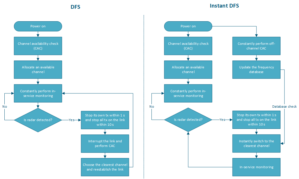
Instant DFS
The DFS mechanism disadvantage is the inability to quickly assess the radio parameters and timely change the operating frequency in accordance to the situation on the air.First solution is to make scanning the air more frequent. In addition, when a radar is detected, a new channel availability check is performed within 60 seconds. During this time, transmission is interrupted and is not restored until it is switched to a new channel with the lowest interference level and is free from radar.
A first solution is to perform the scan more frequently, however, it should be understood that the time spent on updating the information about the radio parameters is not used to transmit data, i.e. the communication system performance decreases.
InfiNet Infinet devices use a proprietary technology called Instant DFS, which allows to obtain current information about the radio state, without breaking interrupting the connection.
Instant DFS
...
operation principles
The Instant DFS operation principle is similar to the described DFS algorithm, but it has the following differences:
- Sequential frequency grid channels scanning is performed continuously, not at a selected time. This allows the device to operate with actual real time information about the radio parameters without stopping the data transfer process. For For the devices of the InfiLINK 2x2 and InfiMAN 2x2 families devices this is implemented using an additional radio module, for the InfiLINK XG family Evolution / InfiMAN Evolution, InfiLINK XG and Quanta 5 families devices - by scanning the air during the guard intervals.
- In case of detecting a freer less interfered frequency channel detection, a switching to another switch with the operating frequency is performed, without interrupting the data transmission process.
- The InfiLINK 2x2 and InfiMAN 2x2 families devices with , which have two radio modules after turned on , distribute among themselves a set of frequency channels that need to be scanned after they are powered-on, so scanning the scan is performed two times faster.
| Center | |||||
|---|---|---|---|---|---|
|
An example of the proprietary Instant DFS mechanism is shown in the video 3:
- The BS and CPE devices are installed and configured to organize establish a wireless link between two buildings , and the Instant DFS technology is activated on the BS. The initial operating frequency selection is similar to the DFS algorithm (see video 1), therefore, it is supposed that the devices have already established a connection and started data exchange.
- Initially, the BS performs data transmission and reception in using frequency channel F3 and scans channel F1. After the scan is completed, the BS device updates the radio status table. Since the F3 channel, which is currently used as an operational is the most free from interferenceclear of interferences, the BS does not make any changes.
- On In the second step, the BS transmits and receives data in using frequency channel F3 and scans channel F2. Interference in The interference level on the F2 frequency channel has significantly improved: the signal level has decreased from -80 dBm to -90 dBm. Now channel F2 performs the best performance is in channel F2, so the BS starts begins the process of changing the operating frequency.
- In order to perform the frequency change without breaking interrupting the connection, the BS generates a broadcast request with an overhead message, which indicates the new operating frequency F2. The frequency is changed on the BS after sending a the broadcast message, and on the CPE after receiving this message.
- On In the third step, the BS performs the transmission and reception of data in the using frequency channel F2 and scans the channel F3. The obtained scan results do not lead to a change in the operating frequency; therefore, data continue continues to transmit be transmitted through the channel F2. Scanning is repeated cyclically in accordance with the set frequency grid.
...
| Center | ||||||||
|---|---|---|---|---|---|---|---|---|
Video 3 - Proprietary Instant DFS algorithm |
Instant DFS application patterns
Devices with Instant DFS support can be used in point-to-point and point-to-multipoint topologies. Note, Please note that the scan results are valid only for the received signal, therefore:
- In point-to-point topologies, it is recommended to use both devices with the Instant DFS technology on both devices. During operation, the devices will exchange the scan results and the decision about the frequency selection will be made taking into account the interference situation on two sitesboth ends.
- If in the point-to-point topology it is not possible to use both two devices with Instant DFS support, then the device with Instant DFS needs to be installed on the site with the most hard highest interference conditionslevels.
- In point-to-multipoint topologies, if it is not possible to use have all the devices with Instant DFS support, the best option would be to install an Instant DFS device as a base station sector.
Instant DFS implementation in the InfiNet devices
Instant DFS proprietary technology support is implemented in devices of for the InfiLINK 2x2 and InfiMAN 2x2 families operating in the 5 GHz frequency band through the additional radio module installation. Lowercase letter "s" in the device part number indicates the presence of the second radio module, for example example, R5000-Mmxbs/5.300.2x500.2x16.
All InfiLINK XG family Evolution / InfiMAN Evolution, InfiLINK XG and Quanta 5 families devices operating in the 5 GHz frequency band support the Instant DFS technology.
Additional information
- DFS configuration process for InfiLINK 2x2 and InfiMAN 2x2 family devices (web / CLI)
- DFS configuration process for InfiLINK Evolution and InfiMAN Evolution family devices (web / CLI)
- Online course "InfiLINK 2x2 / InfiMAN 2x2: Initial Link Configuration and Installation"
- DFS configuration process for InfiLINK XG for the InfiLINK XG family devices (web / CLI)
- DFS configuration process for the Quanta 5 family devices (web)
- Online course "InfiLINK XG Family Product"
- Units Numbering Convention