...
The InfiNet devices of the InfiLINK 2x2 and , InfiMAN 2x2, InfiLINK Evolution, InfiMAN Evolution families have two modules for configuring RIP: rip and arip. The difference between them is in the interoperability with the OSPF protocol, which is not present in the rip module, thus it is recommended to configure the devices using the arip module. Due to the recommendation, this article will describe the RIP configuration using the arip module.
The RIP configuration is performed only via CLI. A separate command shell with several modes is used to configure the RIP protocol (Figure 1). The transition to each mode is performed using the commands with the same name. A detailed description of the commands is available in the Technical documentation.
| Note | ||
|---|---|---|
| ||
An configuration example is given for the InfiLINK 2x2, InfiMAN 2x2 families devices, pay attention to the name of the radio interface on your devices during the scheme implementation. |
| Mode name | Description | |||||||
|---|---|---|---|---|---|---|---|---|
| Basic | The basic RIP mode is used to analyze the output of the diagnostic commands and to switch to the configuration mode. The switching to the basic mode is performed from the WANFleX command shell using the "arip" command.
| |||||||
| RIP configuration | The configuration mode allows to manage the RIP service running on the device and proceed to the configuration modes: router, interfaces or route-maps. The switching to the RIP configuration mode is performed from the basic mode using the "config" command.
| |||||||
| RIP router configuration | In the router configuration mode, basic RIPF settings can be made. The mode allows to configure the announced networks, router ID, etc. The switching to the RIP router configuration mode is performed from the configuration mode using the "router" command.
| |||||||
| RIP interface configuration | The RIP interface configuration mode allows to configure the protocol settings related to a specific interface. The switching to the RIP interface configuration mode is performed from the configuration mode using the "interface IFNAME" command.
| |||||||
| Route-maps configuration | The route-maps configuration mode allows to configure the rules that should be applied to the advertised or received RIP routes. The switching to the RIP route-map configuration mode is performed from the configuration mode using the rule creation command "route-map WORD (deny|permit) <1-65535>".
|
| Center | ||||||||
|---|---|---|---|---|---|---|---|---|
|
...
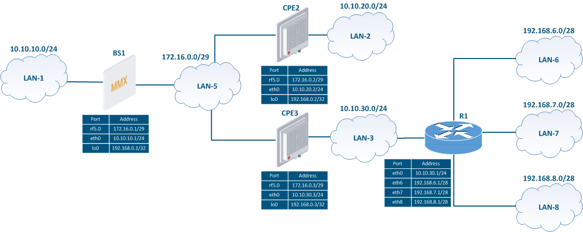
Task: configure the RIP protocol on the wireless devices in order to add information about all the networks in the scheme to the routing table of each router. The BS1 device should be used as default gateway on the CPE2 and CPE3 devices.
| Center |
|---|
Figure 2 - Network scheme for the RIP configuration |

...
| Description | Configure the RIP protocol according to the scheme. Step 1: start the RIP daemon. Step 2: define the interfaces where RIP should be started:
In CPE2's configuration, the range of networks used in RIP will be set as a single entry: 0.0.0.0/0. This entry includes all networks and enables the RIP support on all router's interfaces; when one of the CPE2's interfaces is connected to a new network, this network will be immediately announced via RIP. This approach doesn't require any additional RIP configuration, but decreases the control over the announcements. On the BS1 and CPE3 routers, we will set only those networks that are associated with the interfaces participating in the RIP's operation. Step 3: redistribute the directly connected networks on BS1 and the static routes on the CPE3 router. Step 4: configure passive interfaces. The eth0 interface of CPE3 is connected to the external router R1, therefore it is necessary to block the transmission of the routing information between them. To ensure this, the eth0 interface of CPE3 must be configured as passive. Step 5: announce the default route, specifying BS1 as the gateway. | |||||||
|---|---|---|---|---|---|---|---|---|
| BS1 |
| |||||||
| CPE2 |
| |||||||
| CPE3 |
|
...