...
The IP protocol provides for using 32 bits for addressing nodes in the network, which are usually divided into four octets and written in decimal form, separating octets with dots (Fig. 2). IP addresses examples:
- 10.94.200.7
- 192.17.0.0
- 201.15.2.255
...
- Network address: the address assigned to this network. Often the network addresses are used in device routing tables, as it is shown below. В качестве адреса сети используется наименьший адрес из диапазона разрешённых: в примере The lowest address from the allowed range is used as the network address: in example 1 - 10.94.200.0, в примере in example 2 - 192.17.0.0.Широковещательный адрес: адрес, получателями которого являются все устройства, подключенные к сети. Пакет, в котором в качестве получателя указан широковещательный адрес сети, будет доставлен всем устройствам, подключенным к этой сети. В качестве широковещательного адреса используется наибольший адрес из диапазона разрешённых: в примере
- Broadcast address: recipients of this address are all devices connected to the network. A packet with a network broadcast address set as the destination will be delivered to all devices connected to this network. The highest address from the allowed range is used as the broadcast address: in example 1 - 10.94.200.255, в примере in example 2 - 192.17.0.3.
- Адреса узлов: адреса, которые можно использовать для назначения сетевым интерфейсам устройств, которые подключены к сети. В качестве адресов узлов можно использовать все разрешённые адреса, кроме адреса сети и широковещательного адреса: в примере Nodes addresses: addresses that can be assigned to network interfaces of devices connected to the network. All allowed addresses can be used as node addresses, except for the network address and the broadcast address: in example 1 - 10.94.200.1-10.94.200.254, в примере in example 2 - 192.17.0.1-192.17.0.2.
Место маршрутизатора в сети
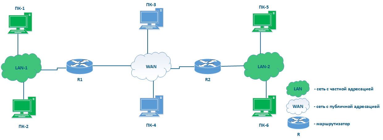
На рисунке 3 отсутствуют элементы, которые связывают сети друг с другом и позволяют передавать данные между сетями, используя IP-адресацию. Такие элементы называются маршрутизаторами (рис. 4). В общем случае маршрутизатор объединяет несколько сетей произвольного типа, а не публичную и частную, как это показано в примере.
Можно выделить следующие ключевые особенности маршрутизаторов:
- Основная функция маршрутизатора - передача данных между сетями, к которым он подключен.
- Подключение маршрутизатора к сети выполняется через подключение к сети одного из интерфейсов маршрутизатора и назначение этому интерфейсу IP-адреса из диапазона разрешённых. В качестве интерфейса может быть использован как физический, так и виртуальный интерфейс.
- При передаче данных маршрутизатор руководствуется таблицей маршрутизации.
- Данные внутри сети передаются с использованием технологии коммутации, а между сетями - маршрутизации, т.е. протоколы IP и Ethernet, как было сказано ранее, дополняют друг друга.
- Для пользовательских данных маршрутизатор является промежуточным устройством и не изменяет адреса источника и получателя. IP-адреса источника и получателя устанавливает источник пакета.
- При поиске получателя в таблице маршрутизации, маршрутизатор анализирует только адрес получателя. Адрес источника в служебном заголовке устанавливается для того, чтобы получатель мог отправить ответный пакет.
- Таблица маршрутизации присутствует не только в специализированных сетевых устройствах, но и конечных узлах. Например, на ПК под управлением ОС Windows таблицу маршрутизации можно увидеть, выполнив команду "route print" в командной строке.
...
...
Place of the router in the network
Figure 3 does not have the elements to connect networks to each other and to transfer data between networks using IP addressing. Such elements are called routers (Figure 4). Usually, a router connects several networks of an arbitrary type, not just public and private, as shown in the example.
The routers have following key features:
- The main function of a router is to transfer data between the connected networks.
- The router is connected to the network by connecting one of the router's interfaces to the network and assigning an IP address from the allowed range to this interface. Both physical and virtual interfaces can be used.
- When transmitting data, the router is guided by routing table.
- Data within the network are transmitted using switching technology, and between networks - routing, i.e. IP and Ethernet are complement each other, as mentioned before.
- For user data, the router is an intermediate device and does not change the source and destination addresses. The packet source sets the source and destination IP addresses.
- The router analyzes only the destination address to find a destination in the routing table.The source address in the service header is set to allow the recipient to send a response packet.
- The routing table is not only in specialized network devices, but also at end nodes. For example, on a Windows software controlled PC, the routing table can be displayed by running the "route print" command at the command line.
| Center |
|---|
Figure 4 - Place of the router in the network |
| Anchor | ||||
|---|---|---|---|---|
|
...
Рассмотрим схему сети (рис. 5), включающую в себя следующие элементы:
...
Routing table
Let's look at the network diagram (Figure 5), which includes the following elements:
- Local network LAN-1 to connect network devices PC-1 and PC-2:
- 192.168.1.0/24 addressing is used in the network;
- ПК-11 ассоциирован с адресом 192.168.1.10/24 is assigned to PC-1;ПК-2 ассоциирован с адресом
- 192.168.1.20/24 is assigned to PC-2;
- R1 ассоциирован с адресом 192.168.1.1/24 is assigned to R1.
- Локальная сеть LAN-3 для подключения пользовательских устройств ПК-3 и ПКLocal network LAN-3 to connect network devices PC-3 and PC-4:
- в сети используется адресация 172172.16.3.0/28 addressing is used in the network;
- ПК-3 ассоциирован с адресом 172.16.3.2/28 is assigned to PC-3;ПК4 ассоциирован с
- адресом 172.16.3.4/28 is assigned to PC-4;
- R3 ассоциирован с адресом 172.16.3.1/28 is assigned to R3.
- Локальная сеть LANLocal network LAN-2 для соединения маршрутизаторов to connect routers R1, R2 и R3 между собойand R3 with each other:
- в сети используется адресация 10.10.2.0/29 addressing is used in the network;
- R1 ассоциирован с адресом 10.10.2.1/29 is assigned to R1;R2 ассоциирован с адресом
- 10.10.10.2.2/29 is assigned to R2;
- R3 ассоциирован с адресом 10.10.2.3 is assigned to R3.
- Подключение маршрутизатора R2 к глобальной сети WAN:на интерфейсе eth0, подключенному к WAN назначен адрес R2 router connection to the WAN global network:
- 45.94.77.7/25 is assigned to eth0 interface connected to WAN.
| Center |
|---|
Рисунок Figure 5 - Пример схемы сети |
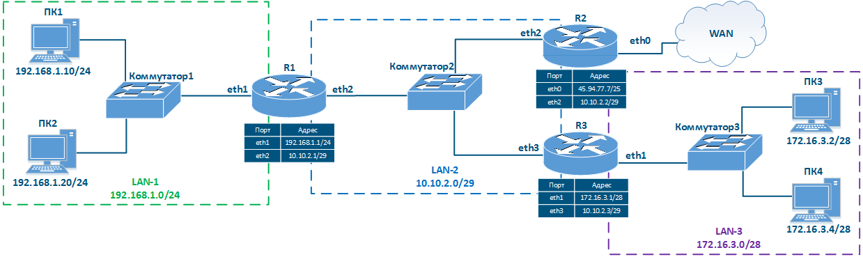
Таблица маршрутизации представляет собой адресный справочник сетей. В ней указывается местонахождение сетей, используемое при передаче пакетов. В таблице маршрутизации может отсутствовать точное местонахождение той или иной сети, однако обязательно указан сетевой интерфейс, через который пролегает путь в сеть назначения. Такая логика используется всеми маршрутизаторами на пути следования трафика, т.е. если на пути прохождения пакета расположено 8 маршрутизаторов, то каждый из них обладает информацией только о следующем маршрутизаторе по ходу следования и эта информация содержится в таблице маршрутизации.
Таблица маршрутизации включает в себя следующие колонки (таблица 2а-в):
...
Network diagram example |
The routing table is an address directory of networks. It contains the location of the networks used for packets transmitting. The routing table may not contain the exact location of a particular network, but there are network interface through which the destination network can be reached. This logic is used by all routers along the traffic path, i.e. if there are 8 routers on the packet path, then each of them has information only about the next router along the way, and this information is contained in the routing table.
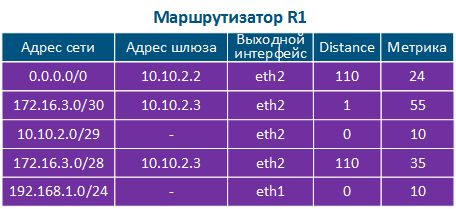
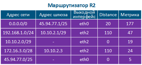
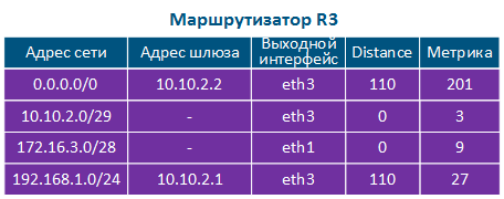
The routing table includes the following columns (Table 2a-c):
- Network address: the packet destination address specified in the service header is checked for belonging to the network whose address is indicated in the table. If the destination belongs to this network, than the current table entry can be used for data transmission.
- Gateway address: the next router address there the packet will be forwarded.
- Output interface: the network interface for the packet transmission.
- Distance: in networks with redundant communication channels, there are several paths to the same network. These routes can be obtained from one or several sources, however, only one of these routes should be placed in the routing table. To prioritize routes from different sources, use the Administrative Distance parameter (or Distance), which means the level of trust to this source. The route from the source with the lowest Distance value will be added to the routing table, as a lower Distance value means a higher level of trust. General recommendations for Distance values are followed by most manufacturers of network equipment (Table 3).
- Metric: a route to the same network can be obtained not only from different sources, as mentioned above, but also from the same. These routes are prioritized using Metric value when added to the routing table. Each routes source calculates the metric using different algorithms, so the metrics from different sources cannot be directly compared.
| Center | |||||||||||||||||
|---|---|---|---|---|---|---|---|---|---|---|---|---|---|---|---|---|---|
| |||||||||||||||||
| Источник маршрута | Distance | ||||||||||||||||
| непосредственно подключенные сети | 0 |
|
| Route source | Distance |
|---|---|
| directly connected networks | 0 |
| static route | 1 |
| External BGP | 20 |
| OSPF | 110 |
| RIP | 120 |
| ODR | 160 |
Таблица Table 3 - Распределение значений Distance в зависимости от источника маршрутаDistance values depending on route source
Использование таблицы маршрутизации
...