Table of contents
Introduction
The main task of switching is to ensure nodes connectivity within one network (see. InfiLINK 2x2 and InfiMAN 2x2: Switching). To organize communication between networks, different class of devices (routers) must be used (see Figure 1). This article describes the applications areas and configuration of Infinet devices used as routers.
Terminology
- Switching - the process of connecting subscribers through intermediate devices. In most modern networks, frame switching is done based on the Ethernet header (destination MAC address and vlan ID). In example (Figure 1a) data exchange between PC-1 and PC-2 is performed based on MAC addresses. In this article, the terms switching and L2 data transmission technology are identical.
- Switch - the device that performs switching.
- Routing - the process of determining the data transmission path between nodes in different networks, which is the best according to some criteria. Most modern networks route packets based on the IP header (destination IP address). In example (Figure 1b) data exchange between PC-1 and PC-2 is performed based on IP addresses. n this article, the terms routing and L3 data transmission technology are identical.
- Router - the device that performs routing.
- Local network - the network part that is in the responsibility area of the organization. The organization's employees are responsible for assigning IP addresses to devices on this network, an address conflict is very unlikely.
- Global network - network having global scale. Usually, the Internet is understood as a global network. Since many local networks are connected to the global network, the IP addresses allocation is performed centrally by special organizations.
Switching
Let's look at the difference in processing service headers for data transmission by switching and routing using an example (Figure 1).
In the scenario when PC-1 sends data to PC-2 (Figure 1a), PC-1 fills in the service fields following way:
- Destination MAC address: MAC address PC-2 - MAC-2;
- Source MAC address: MAC address PC-1 - MAC-1;
- Destination IP address: IP address PC-2 - IP-2;
- Source IP address: IP address PC-1 - IP-1.
The switch receives a frame from PC-1 and redirects it to PC-2 in accordance with the switching table. Thus, data transmission is performed based on the Ethernet service header, since transmission is at the data link level. This mechanism is called switching.
In the scenario when PC-1 sends data to PC-3 (Figure 1b), PC-1 fills in the frame service fields following way:
- Destination MAC address: router MAC address - MAC-R2;
- Source MAC address: MAC address PC-1 - MAC-1;
- Destination IP address: IP address PC-3 - IP-3;
- Source IP address: IP address PC-1 - IP-1.
The switch receives such a frame and transmits it to the router in accordance with the switching table. The router receives the frame, decapsulates the IP packet and transmits it to LAN-2. In this case, service headers will be set in the following way:
- Destination MAC address: MAC address PC-3 - MAC-3;
- Source MAC address: outer MAC address - MAC-R2;
- Destination IP address: IP address PC-3 - IP-3;
- Source IP address: IP address PC-1 - IP-1.
Note that the IP packet header is left unchanged, the receiver and sender MAC addresses in the Ethernet frame header are changed. This operation was performed because MAC addresses are used to transfer data within the same local network, i.e. when transferring data between different local networks, the MAC addresses will always be replaced. This data transfer mechanism is called routing.
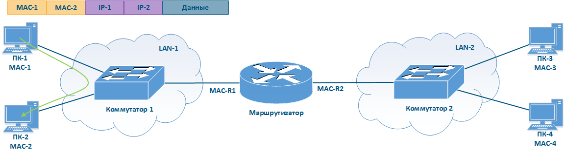
Figure 1a - Example of data transmission from PC-1 to PC-2
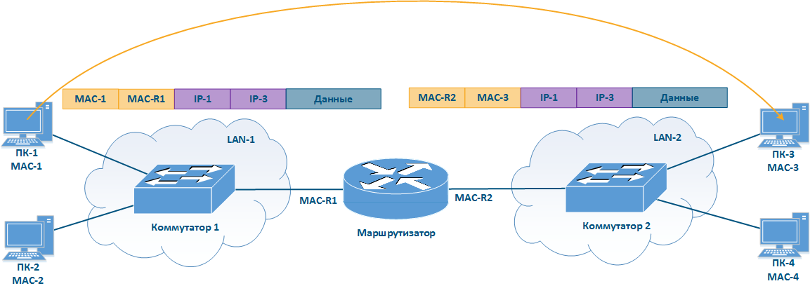
Figure 1b - Example of data transmission from PC-1 to PC-3
Routing
The main networks function is the ability to organize communication between arbitrary nodes connected to this network. Using for these tasks the packet switching technologies associated with the link layer of network interaction model has a number of disadvantages:
- There is a risk of loops appearance when using some data-link protocols such as Ethernet. The risk can be minimized using third party tools such as STP, but is not limited by standard Ethernet facilities.
- The broadcast traffic amount depends on the number of devices connected to the network. To ensure that the amount of broadcast traffic in the total traffic is not large, the devices number connected to one broadcast domain should be limited. Thus, all network devices cannot be connected to the same broadcast domain, which makes impossible using L2 layer protocols to organize global device connectivity.
- Switches to transmit data operate on Ethernet frames, the headers of which contain the source and destination devices MAC addresses. Each entry in the switching table contains the MAC address of the device interface and does not support the mechanism for grouping these addresses. Thus, ensuring global connectivity will require switching tables, which include the MAC addresses of all devices in the world at each network node.
The IP network layer protocol, which is widely used to provide connectivity in large and global networks, lacks these disadvantages. IP is not a replacement for Ethernet, these protocols work together and perform different functions: Ethernet provides data transfer within the communication channel, IP is responsible for global addressing and node communication.
Currently, two versions of the IP protocol have become widespread: IPv4 and IPv6. Since Infinet devices currently support only the IPv4 protocol, further article will contain the description of only this version.
IP protocol
IP address
The IP protocol provides for using 32 bits for addressing nodes in the network, which are usually divided into four octets and written in decimal form, separating octets with dots (Fig. 2). IP addresses examples:
- 10.94.200.7
- 192.17.0.0
- 201.15.2.255
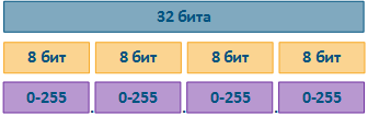
Figure 2 - IP address structure
Network mask
IP provides the grouping of addresses on a network using network masks. A netmask is applied to an IP address, dividing it in two parts: a network ID and a host ID. Devices connected to the same network will have the same network ID and different host IDs. To ensure the network ID is matching on all devices, use the same network mask values when configuring devices. Host IDs set allows inferring the number of devices that can be connected to this network and their IP addresses.
The network mask has 32 bits and is written in the same way as the IP address with one difference: the mask consists of a one bits sequence followed by zero bits, i.e. the set of masks is preset and contains 33 values: from 0 to 32. The finite range of possible values allows to write the network mask in an abbreviated form, in which the number of single bits in the mask is indicated after a slash (see the table below).
One bits in the network mask define the network identifier: the bits of the IP address corresponding to one bit values of the mask must be fixed and cannot be changed. The remaining bits of the IP address, corresponding to the zero bit values of the mask, can take arbitrary values and determine the host ID.
When configuring devices connected to the network, IP addresses are not used without the network mask, since routing rules imply a different approach when transferring data to a device from "own" network and to other devices (see Switching). Note that the network mask is indicated in the device configuration and is not transmitted in the service header of the IP packet.
| Example | Parameter | Decimal format | Binary format | Abbreviated format |
|---|---|---|---|---|
Example 1 | IP address | 10.94.200.7 | 00001010.01011110.11001000.00000111 | - |
| Network mask | 255.255.255.0 | 11111111.11111111.11111111.00000000 | /24 | |
| Minimal address | 10.94.200.0 | 00001010.01011110.11001000.00000000 | - | |
| Maximal address | 10.94.200.255 | 00001010.01011110.11001000.11111111 | - | |
Example 2 | IP address | 192.17.0.0 | 11000000.00010001.00000000.00000000 | - |
| Network mask | 255.255.255.252 | 11111111.11111111.11111111.11111100 | /30 | |
| Minimal address | 192.17.0.0 | 11000000.00010001.00000000.00000000 | - | |
| Maximal address | 192.17.0.3 | 11000000.00010001.00000000.00000011 | - |
Table 1 - Network mask examples
Addresses types
The IP address can be divided according to several criteria:
- by application area;
- by belonging.
By the application area, addresses can be divided in two large groups: public and private (Figure 3). Global connectivity can only be established between public addresses, i.e. private addressing is used on the enterprise local network, and public addressing is used on the Internet. The public address is unique, private addresses can be reused, i.e. devices PC-2 and PC-6 may have the same address and this is not a problem, since there is no connectivity between LAN-1 and LAN-2. However, addressing within the same local network must be unique, i.e. the addresses of PC-5 and PC-6 must be different.
In addition to public and private addresses, several service ranges are allocated, for example, to transmit multicast traffic, loopback interface traffic, etc.
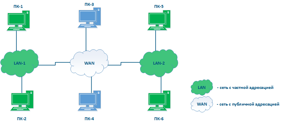
Figure 3 - An example of various types networks connecting
By belonging in any network, the following addresses can be distinguished:
- Network address: the address assigned to this network. Often the network addresses are used in device routing tables, as it is shown below. The lowest address from the allowed range is used as the network address: in example 1 - 10.94.200.0, in example 2 - 192.17.0.0.
- Broadcast address: recipients of this address are all devices connected to the network. A packet with a network broadcast address set as the destination will be delivered to all devices connected to this network. The highest address from the allowed range is used as the broadcast address: in example 1 - 10.94.200.255, in example 2 - 192.17.0.3.
- Nodes addresses: addresses that can be assigned to network interfaces of devices connected to the network. All allowed addresses can be used as node addresses, except for the network address and the broadcast address: in example 1 - 10.94.200.1-10.94.200.254, in example 2 - 192.17.0.1-192.17.0.2.
Place of the router in the network
Figure 3 does not have the elements to connect networks to each other and to transfer data between networks using IP addressing. Such elements are called routers (Figure 4). Usually, a router connects several networks of an arbitrary type, not just public and private, as shown in the example.
The routers have following key features:
- The main function of a router is to transfer data between the connected networks.
- The router is connected to the network by connecting one of the router's interfaces to the network and assigning an IP address from the allowed range to this interface. Both physical and virtual interfaces can be used.
- When transmitting data, the router is guided by routing table.
- Data within the network are transmitted using switching technology, and between networks - routing, i.e. IP and Ethernet are complement each other, as mentioned before.
- For user data, the router is an intermediate device and does not change the source and destination addresses. The packet source sets the source and destination IP addresses.
- The router analyzes only the destination address to find a destination in the routing table.The source address in the service header is set to allow the recipient to send a response packet.
- The routing table is not only in specialized network devices, but also at end nodes. For example, on a Windows software controlled PC, the routing table can be displayed by running the "route print" command at the command line.
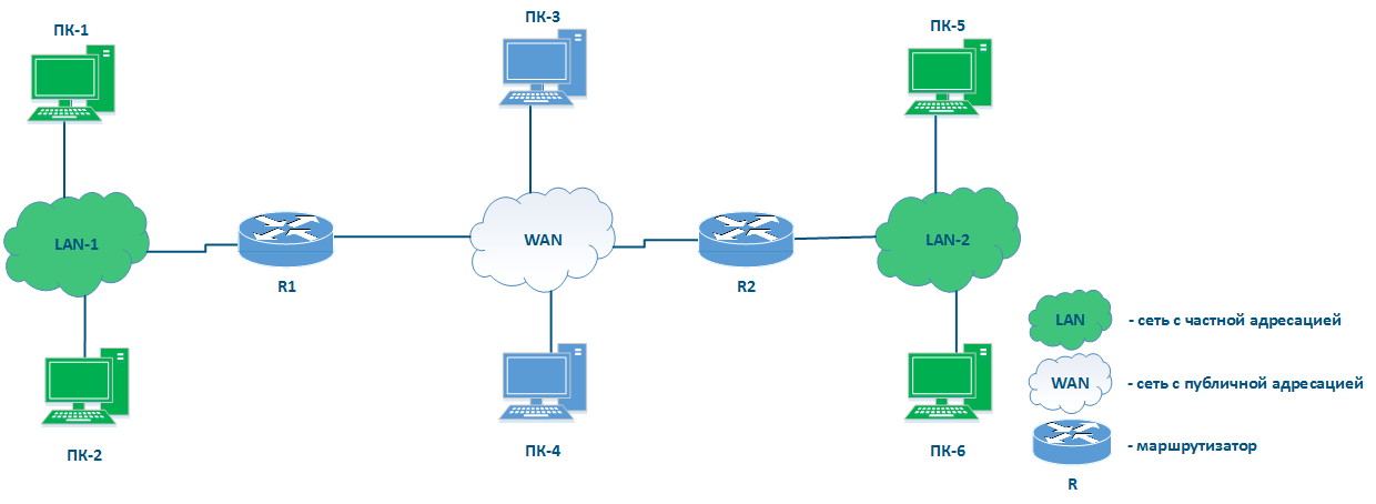
Figure 4 - Place of the router in the network
Routing table
Let's look at the network diagram (Figure 5), which includes the following elements:
- Local network LAN-1 to connect network devices PC-1 and PC-2:
- 192.168.1.0/24 addressing is used in the network;
- 192.168.1.10/24 is assigned to PC-1;
- 192.168.1.20/24 is assigned to PC-2;
- 192.168.1.1/24 is assigned to R1.
- Local network LAN-3 to connect network devices PC-3 and PC-4:
- 172.16.3.0/28 addressing is used in the network;
- 172.16.3.2/28 is assigned to PC-3;
- 172.16.3.4/28 is assigned to PC-4;
- 172.16.3.1/28 is assigned to R3.
- Local network LAN-2 to connect routers R1, R2 and R3 with each other:
- 10.10.2.0/29 addressing is used in the network;
- 10.10.2.1/29 is assigned to R1;
- 10.10.2.2/29 is assigned to R2;
- 10.10.2.3 is assigned to R3.
- R2 router connection to the WAN global network:
- 45.94.77.7/25 is assigned to eth0 interface connected to WAN.
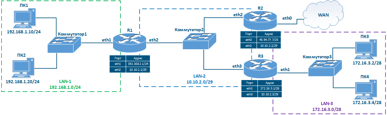
Figure 5 - Network diagram example
The routing table is an address directory of networks. It contains the location of the networks used for packets transmitting. The routing table may not contain the exact location of a particular network, but there are network interface through which the destination network can be reached. This logic is used by all routers along the traffic path, i.e. if there are 8 routers on the packet path, then each of them has information only about the next router along the way, and this information is contained in the routing table.
The routing table includes the following columns (Table 2a-c):
- Network address: the packet destination address specified in the service header is checked for belonging to the network whose address is indicated in the table. If the destination belongs to this network, than the current table entry can be used for data transmission.
- Gateway address: the next router address there the packet will be forwarded.
- Output interface: the network interface for the packet transmission.
- Distance: in networks with redundant communication channels, there are several paths to the same network. These routes can be obtained from one or several sources, however, only one of these routes should be placed in the routing table. To prioritize routes from different sources, use the Administrative Distance parameter (or Distance), which means the level of trust to this source. The route from the source with the lowest Distance value will be added to the routing table, as a lower Distance value means a higher level of trust. General recommendations for Distance values are followed by most manufacturers of network equipment (Table 3).
- Metric: a route to the same network can be obtained not only from different sources, as mentioned above, but also from the same. These routes are prioritized using Metric value when added to the routing table. Each routes source calculates the metric using different algorithms, so the metrics from different sources cannot be directly compared.
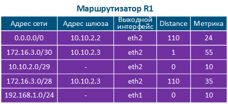
Table 2a - The R1 routing table example
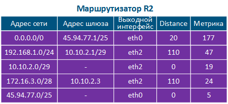
Table 2b - The R2 routing table example

Table 2c - The R3 routing table example
| Route source | Distance |
|---|---|
| directly connected networks | 0 |
| static route | 1 |
| External BGP | 20 |
| OSPF | 110 |
| RIP | 120 |
| ODR | 160 |
Table 3 - Distance values depending on route source
Использование таблицы маршрутизации
На пути следования пакета каждый из маршрутизаторов применяет алгоритм использования таблицы маршрутизации. Этот алгоритм выглядит следующим образом:
- Этап 1: адрес получателя проверяется на принадлежность сетям, записи о которых присутствуют в таблице маршрутизации.
- Этап 2: среди записей, удовлетворяющих требованию этапа 1, выбирается "наиболее узкий маршрут", т.е. запись с максимальным значением маски сети. Например, маска /24 уже, чем /8.
- Этап 3: если на этапе 2 отобрано несколько записей таблицы маршрутизации с одинаковыми масками сети, выполняется сравнение параметра Distance. Чем меньше значение этого параметра, тем выше приоритет маршрута.
- Этап 4: если на этапе 3 отобрано несколько записей таблицы маршрутизации с одинаковыми значениями Distance, выполняется сравнение метрик. Чем меньше значение метрики, тем выше приоритет маршрута.
- Этап 5: если ни одна из записей таблицы маршрутизации не удовлетворяет требованиям этапа 1 и отсутствует маршрут по умолчанию, то пакет отбрасывается.
Примеры использования таблицы маршрутизации
Рассмотрим примеры использования таблицы маршрутизации в различных сценариях (рис. 6а-в).
Сценарий 1 - подключение ПК1 к FTP-серверу, запущенному на ПК2 (источник - 192.168.1.10, получатель - 192.168.1.20)
- Этап 1а: ПК1 формирует пакет с адресом получателя ПК2 и передаёт его на обработку канальному уровню сетевого интерфейса.
- Этап 1б: Канальный уровень сетевого интерфейса ПК1 проверяет принадлежность получателя к сети источника. Поскольку ПК1 и ПК2 принадлежат одной сети, то в заголовке Ethernet устанавливается MAC-адрес сетевого интерфейса ПК2. Сформированный кадр отправляется Коммутатору1.
- Этап 1в: Коммутатор передаёт кадр ПК2 в соответствии с таблицей коммутации.
Данные передаются в рамках одной сети с использованием технологий коммутации, поэтому маршрутизатор R1 в этом процессе не участвует.
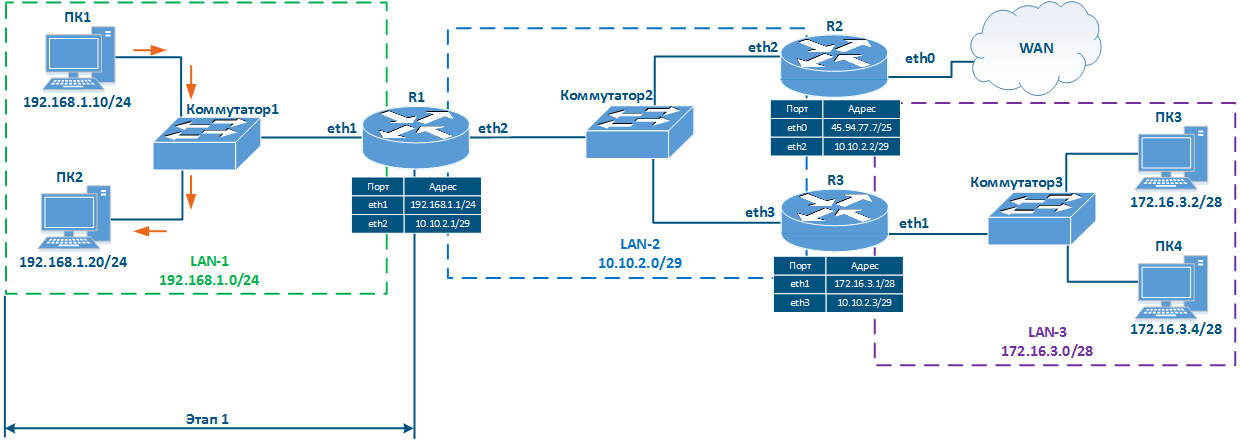
Рисунок 6а - Передача пакета от ПК1 к ПК2
Сценарий 2 - проверка доступности ПК3 со стороны ПК1 (источник - 192.168.1.10, получатель - 172.16.3.2)
- Этап 1а: ПК1 формирует пакет с адресом получателя ПК3 и передаёт его на обработку канальному уровню сетевого интерфейса.
- Этап 1б: Канальный уровень сетевого интерфейса ПК1 принадлежность получателя к сети источника. ПК1 и ПК3 принадлежат разным сетям, поэтому в качестве MAC-адреса получателя в заголовке Ethernet указывается MAC-адрес маршрутизатора R1. Сформированный кадр отправляется Коммутатору 1.
- Этап 1в: Коммутатор1 передаёт кадр R1 в соответствии с таблицей коммутации.
- Этап 2а: Маршрутизатор R1 анализирует таблицу маршрутизации: адресу получателя удовлетворяют две записи, 172.16.3.0/28 и 172.16.3.0/30. Т.к. маска /30 уже, чем /28, то R1 будет перенаправлять пакет в сеть 172.16.3.0/30. Обратите внимание, если бы получателем пакета было устройство ПК4, то использовалась бы другая запись в таблице маршрутизации, несмотря на то, что ПК3 и ПК4 относятся к одной сети.
- Этап 2б: Маршрутизатор R1 передаёт кадр Ethernet маршрутизатору R3. IP-адреса источника и получателя остаются без изменений, MAC-адрес источника устанавливается равным MAC-адресу интерфейса eth2 R1, MAC-адрес получателя - MAC-адресу интерфейса eth3 R3.
- Этап 2в: Коммутатор передаёт полученный Ethernet-кадр маршрутизатору R3.
- Этап 3а: Маршрутизатор R3 анализирует таблицу маршрутизации: адресу получателя удовлетворяет сеть 172.16.3.0/28.
- Этап 3б: Маршрутизатор R3 отправляет Ethernet-кадр в направлении Коммутатора3. IP-адреса источника и получателя остаются без изменений, MAC-адрес источника устанавливается равным MAC-адресу интерфейса eth1 R3, MAC-адрес получателя - MAC-адресу интерфейса сетевого интерфейса ПК3.
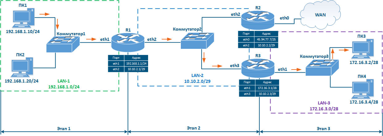
Рисунок 6б - Передача пакета от ПК1 к ПК3
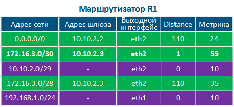
Таблица 4а - Пример таблицы маршрутизации маршрутизатора R1

Таблица 4б - Пример таблицы маршрутизации маршрутизатора R2
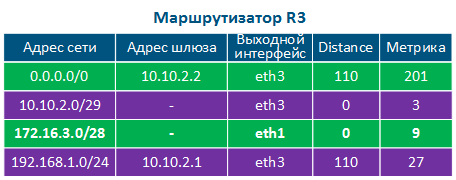
Таблица 4в - Пример таблицы маршрутизации маршрутизатора R3
Сценарий 3 - переход на сайт "infinet.ru" с ПК1 (источник - 192.168.1.10, получатель - 82.151.200.119)
- Этап 1: ПК1 формирует пакет с адресом получателя 82.151.200.119, что соответствует IP-адресу сервера, по которому доступен сайт infinet.ru. Пакет отправляется маршрутизатору R1.
- Этап 2: Маршрутизатор R1 анализирует таблицу маршрутизации: в таблице отсутствуют сети, удовлетворяющие адресу получателя, поэтому необходимо использовать маршрут по умолчанию. Маршрутизатор отправляет пакет в направлении R2.
- Этап 3: Маршрутизатор R2 анализирует таблицу маршрутизации: нет записей, удовлетворяющих адресу получателя, поэтому используется маршрут по умолчанию и пакет отправляется на маршрутизатор, находящийся за пределами локальной сети (в сеть WAN).

Рисунок 6в - Передача пакета от ПК1 к серверу infinet.ru
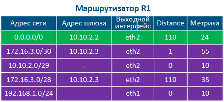
Таблица 4а - Пример таблицы маршрутизации маршрутизатора R1
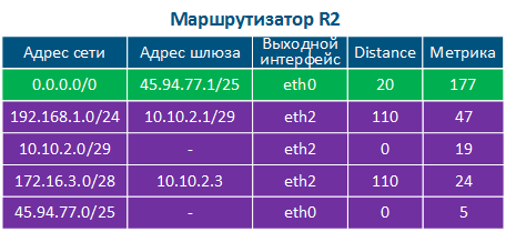
Таблица 4б - Пример таблицы маршрутизации маршрутизатора R2

Таблица 4в - Пример таблицы маршрутизации маршрутизатора R3
Заполнение таблицы маршрутизации
Говоря о механизмах заполнения таблицы маршрутизации стоит ввести два термина:
- RIB (routing information base - база данных о маршрутизации) - совокупность маршрутной информации, полученной из всех источников.
- FIB (forwarding information base - база данных о перенаправлении) - таблица перенаправления данных, используемая для обработки транзитного трафика. FIB формируется из RIB путём фильтрации и объединения маршрутной информации (рис. 7).
Источниками маршрутной информации, формирующих RIB, являются:
- Маршруты операционной системы: служебные сети, используемые операционной системой устройства. Например, к таким сетям относится сеть петлевых интерфейсов 127.0.0.0/8.
- Непосредственно присоединённые сети: сети, к которым устройство подключено непосредственно, т.е. интерфейсы устройства ассоциированы с IP-адресами, которые принадлежат этим сетям. Distance маршрутов такого типа минимальный и равен 0 (таблица 2а-в).
- Статические маршруты: маршруты, добавленные в таблицу вручную. Distance маршрутов такого типа равен 1 (таблица 2а).
- Протоколы динамической маршрутизации: маршруты, полученные с помощью протоколов динамической маршрутизации. За каждым из протоколов динамической маршрутизации закреплено значение Distance, примеры которых представлены в таблице 3.
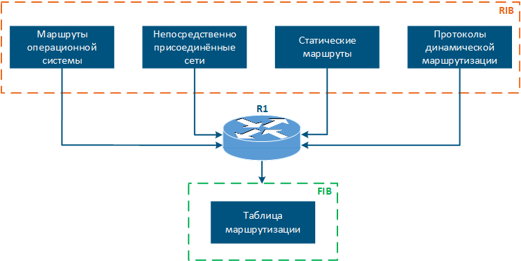
Рисунок 7 - Источники маршрутной информации
Таблица маршрутизации в устройствах Инфинет
В зависимости от семейства, устройства Инфинет поддерживают различные источники маршрутной информации:
| Источник маршрутной информации | InfiLINK 2x2 | InfiMAN 2x2 | InfiLINK XG | InfiLINK XG 1000 | Vector 5 | Vector 70 | |
|---|---|---|---|---|---|---|---|
| Маршруты операционной системы | + | + | + | + | + | + | |
| Непосредственно присоединённые сети | трафик управления | + | + | + | + | + | + |
| пользовательский трафик | + | + | - | - | - | - | |
| Статические маршруты | трафик управления | + | + | + | + | + | + |
| пользовательский трафик | + | + | - | - | - | - | |
Протоколы динамической маршрутизации | OSPF | + | + | - | - | - | - |
| ODR | + | + | - | - | - | - | |
| RIP | + | + | - | - | - | - | |
Таблица 6 - Сравнительная характеристика источников маршрутной информации для устройств Инфинет
Отображение таблицы маршрутизации
Далее, по ходу статьи, мы будем использовать инструменты вывода и анализа маршрутной информации. Эти инструменты зависят от семейства устройств и будут представлены ниже.
Таблица маршрутизации устройств семейств InfiLINK 2x2, InfiMAN 2x2
Устройства семейств InfiLINK 2x2, InfiMAN 2x2 поддерживают настройку маршрутизации как для трафика управления, так и для пользовательского трафика, причём поддерживаются статические маршруты и протоколы динамической маршрутизации.
Вывод маршрутной информации осуществляется двумя способами:
- Web-интерфейс: переход в раздел "Настройки сети → Параметры маршрутизации" (рис. 8а). Интерфейс позволяет просмотреть только статические маршруты.
- Командная строка: команда "nestat -r" выводит данные FIB. Кроме того, существуют команды, позволяющие оценить маршрутную информацию по отдельным источникам, о которых пойдёт речь в соответствующих разделах.
Unknown node#1> netstat -r
Routing tables
Destination        Gateway            Flags     Refs     Use  Interface
10.10.10.0/24      link#6             UC          0        0  svi1
10.10.10.101       00:0c:29:40:72:d0  UHL         0        1  svi1
10.10.10.254       link#6             UHL         0        0  svi1
10.10.20.0/24      link#2             UC          0        0  eth0
10.10.20.101       00:0c:29:40:72:d0  UHL         1     1307  eth0
127.0.0.1          127.0.0.1          UH          1        0  lo0
224.0.0.0/8        127.0.0.1          UGS         0        0  lo0
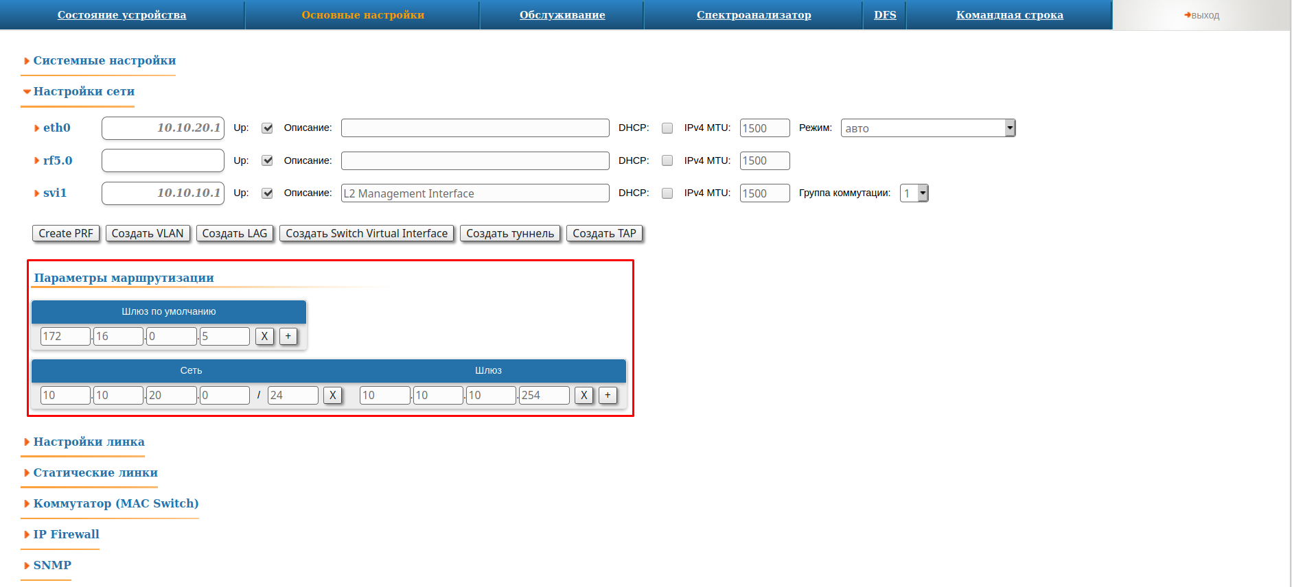
Рисунок 8а - Пример просмотра маршрутной информации на устройствах семейств InfiLINK 2x2, InfiMAN 2x2
Таблица маршрутизации устройств семейств InfiLINK XG, InfiLINK XG 1000
Устройства семейств InfiLINK XG, InfiLINK XG 1000 поддерживают только настройку маршрутизации для трафика управления. Можно указать шлюз по умолчанию и добавить статические маршруты. Вывод таблицы маршрутизации осуществляется двумя способами:
- Web-интерфейс: переход в раздел "Сетевой доступ" (рис. 8б).
- Командная строка: выполнение команды "nestat -r".
#1> netstat -r
Routing tables
Destination        Gateway            Flags     Refs     Use  Interface
10.10.10.0/24      link#2             UC          0        0  mgmt
10.10.10.101       00:0c:29:40:72:d0  UHL         1      512  mgmt
10.10.10.254       link#2             UHL         1        0  mgmt
10.10.20.0/24      10.10.10.254       UGS         0        0  mgmt
127.0.0.1          127.0.0.1          UH          0        0  lo0
224.0.0.0/8        127.0.0.1          UGS         0        0  lo0
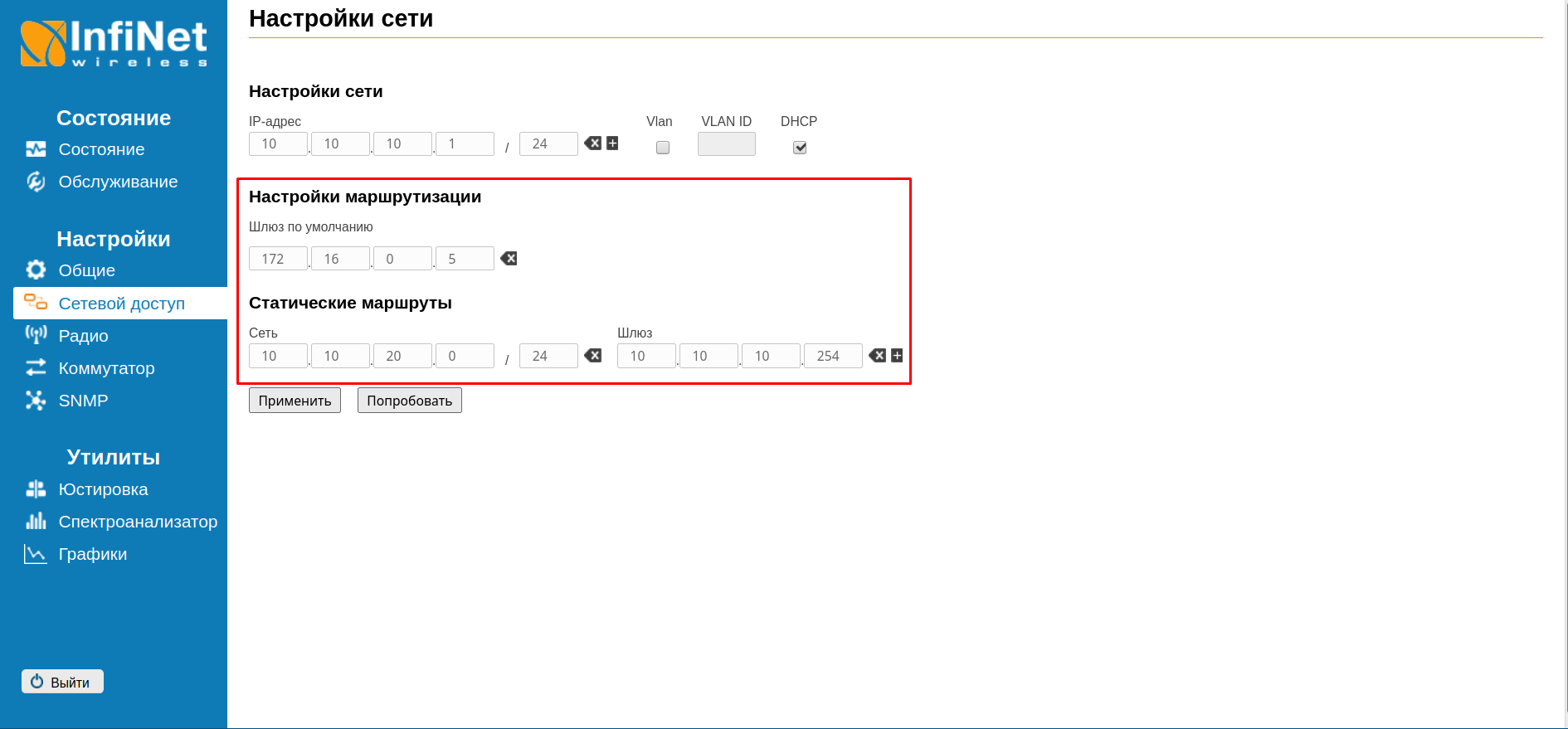
Рисунок 8б - Пример просмотра маршрутной информации на устройствах семейств InfiLINK XG, InfiLINK XG 1000
Таблица маршрутизации устройств семейств Vector 5, Vector 70
Устройства семейств Vector 5, Vector 70 поддерживают только настройку маршрутизации для трафика управления, позволяя указать шлюз по умолчанию. Вывод таблицы маршрутизации осуществляется двумя способами:
- Web-интерфейс: переход в раздел "Сетевой доступ" (рис. 8в).
- Командная строка: выполнение команды "netstat -r".
#1> netstat -r
Routing tables
Destination        Gateway            Flags     Refs     Use  Interface
10.10.10.0/24      link#2             UC          0        0  eth0
10.10.10.101       00:0c:29:40:72:d0  UHL         5     3222  eth0
127.0.0.1          127.0.0.1          UH          0        0  lo0
224.0.0.0/8        127.0.0.1          UGS         0        0  lo0
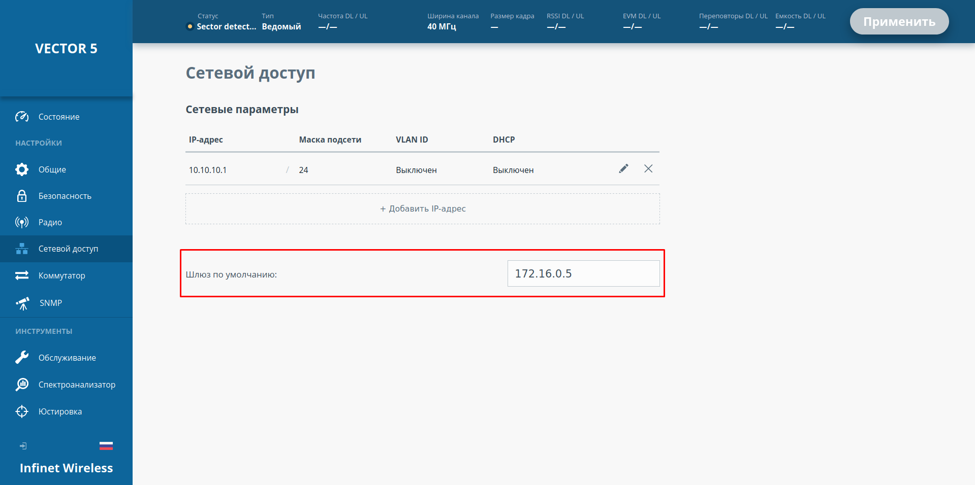
Рисунок 8в - Пример просмотра маршрутной информации на устройствах семейства Vector 5, Vector 70
Продолжение статьи
Продолжение статьи доступно по ссылке: Статическая маршрутизация.
Дополнительные материалы
Онлайн-курсы
- Предварительная настройка и установка устройств семейств InfiLINK 2x2 и InfiMAN 2x2
- Коммутация в устройствах семейств InfiLINK 2x2 и InfiMAN 2x2.
- Устройства семейства InfiLINK XG
- Vector 5: установка и настройка
Вебинары
- Типовые сценарии настройки маршрутизации в устройствах Инфинет. Часть 1.
- Типовые сценарии настройки маршрутизации в устройствах Инфинет, часть 2.